
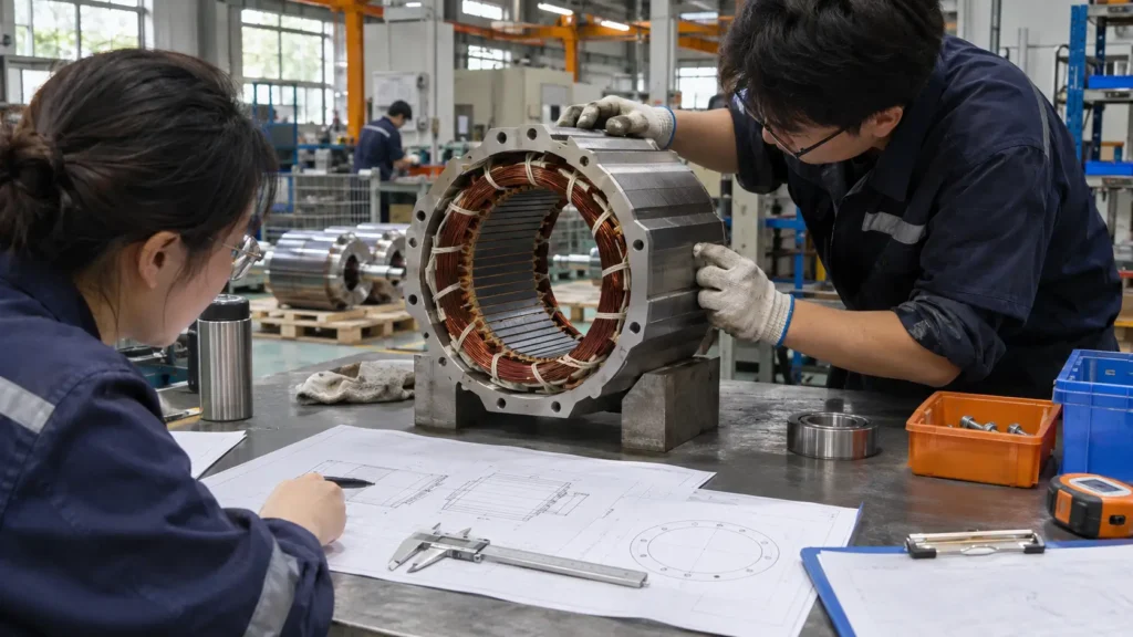
When international OEMs, system integrators, and industrial engineering leads approach a Chinese Permanent Magnet Synchronous Motor (PMSM) manufacturer for a custom project, the core commercial question is whether the factory can translate specific machine operating conditions into a repeatable electromagnetic, mechanical, and thermal build without hidden cost overruns or batch drift. A company name, an extensive standard catalog, or an unstandardized unit price quotation does not establish custom manufacturing capability. Standard catalog supply and project specific engineering are distinct factory operations; on this page, the engineering and production teams at Hiest explain how we evaluate custom feasibility, lock design boundaries, execute prototype to batch transitions, and calculate NRE tooling, unit cost, Minimum Order Quantity (MOQ), and lead time. To maintain strict technical accuracy, this page does not publish generic price tables, arbitrary MOQ figures, or blanket certification promises, and external market summaries should never be treated as verified factory specifications. All model specific parameters, platform boundaries, compliance scopes, and commercial terms are confirmed directly through our formal engineering review against your project documentation.
We structure this page around the exact engineering, manufacturing, and commercial variables that govern a custom motor order on our shop floor. We begin by explaining what separates an actual custom motor manufacturer from a catalog assembler and where we draw the line between standard platform adaptation and full electromagnetic redesign. Next, we detail the physical customization boundaries across speed, torque, drive integration, and environmental sealing, followed by the six engineering input categories our team requires to calculate an accurate quotation. We then lay out our internal design review, quality traceability, and version control protocols, map the production gates from soft tooled prototypes to hard tooled batch release, and break down how raw materials, tooling amortization, and test scopes determine your final price, MOQ, and delivery schedule. Finally, we address post order manufacturing risks and show how our engineering team structures technical acceptance criteria so your quotation baseline remains transparent and verifiable.
What Makes a PMSM Manufacturer a Custom Motor Manufacturer?
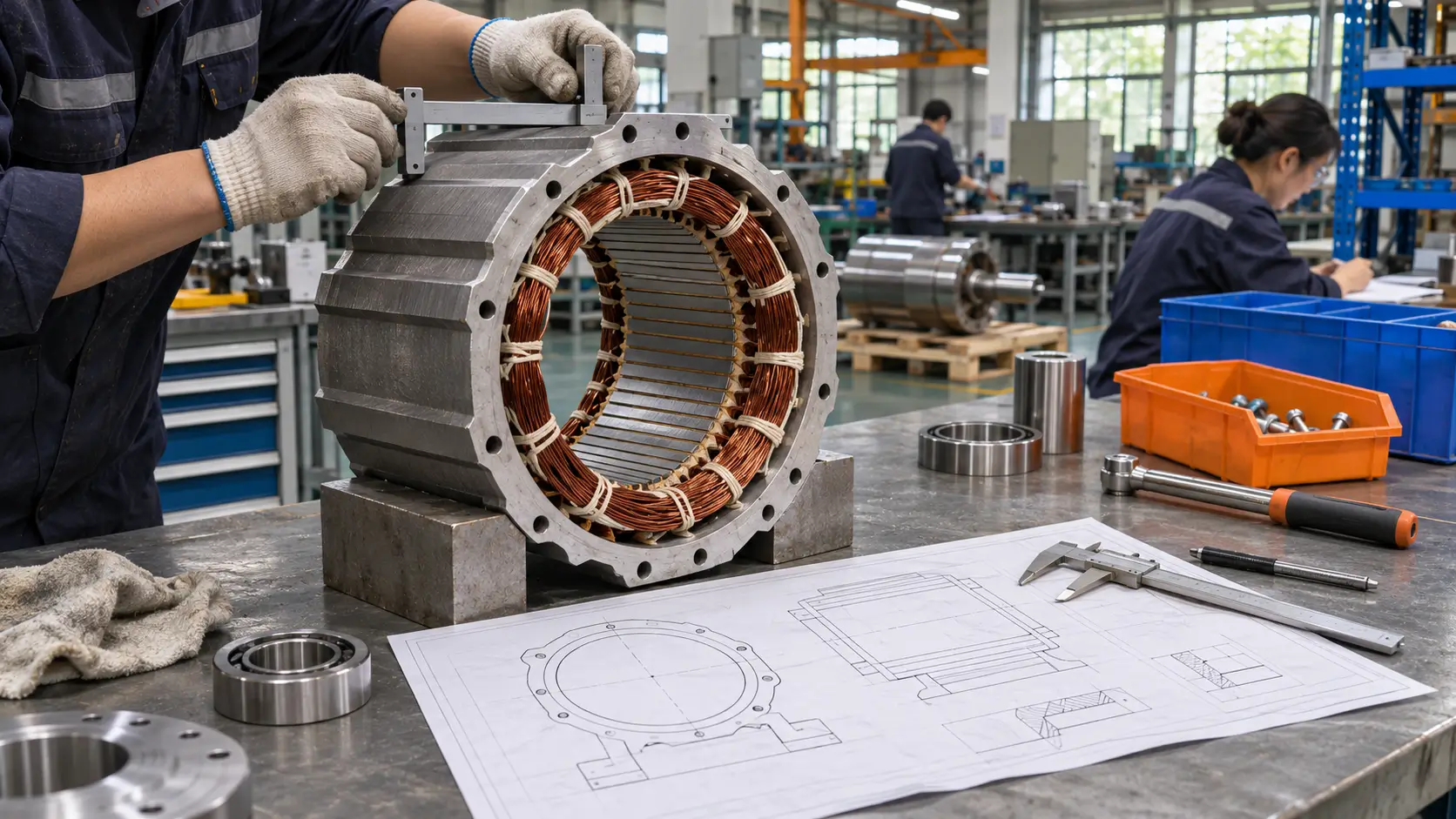
From a manufacturing standpoint, true custom PMSM capability means operating an in house engineering and production closed loop that converts raw machine load profiles, speed ranges, VFD constraints, and mounting envelopes into validated magnetic circuits, winding specifications, thermal paths, and controlled assembly processes. Maintaining a large catalog of standard frames, holding off the shelf inventory, or printing an OEM logo on a nameplate represents standard distribution and commercial assembly, not custom motor manufacturing. Whereas a trading company or basic assembler can only select the closest catalog rating and modify external lead wires, a custom manufacturer calculates slot pole combinations, adjusts stator winding turns to match drive voltage ceilings, machines custom bearing housings, validates thermal rise on a dynamometer, and locks the Bill of Materials (BOM) under formal revision control.
Public product pages and standard brochures only show nominal frame intervals because actual customization limits depend on how electromagnetic, thermal, and mechanical variables interact under your specific duty cycle. When engineering leads review Hiest three phase permanent magnet synchronous motors against their load, operating speed, electrical supply, and machine interfaces, our technical team evaluates custom feasibility across six manufacturing domains including magnetic circuit and rotor topology, stator winding parameters and back EMF matching, mechanical mounting and shaft interfaces, thermal dissipation and insulation class, ingress protection and environmental sealing, and routine versus type test execution.
| Customization Tier | Applicable Project Conditions | Factory Engineering & Tooling Impact | Engineering Confirmation Items |
|---|---|---|---|
| Cosmetic, Nameplate & Harness Adjustment | Rated torque, speed, and mounting match existing catalog models; only paint color, cable length, connector type, or OEM labeling changes. | No change to stator/rotor laminations or magnetic circuit; impacts only final assembly BOM, outgoing visual inspection, and packaging. | Connector pinout drawings, cable specification, nameplate artwork sign off, and batch labeling traceability. |
| Standard Platform Adaptation | Target torque and speed fall within an existing lamination platform; requires winding turn adjustments, shaft extension edits, or custom flange adapters. | Retains existing stator/rotor stamping dies; requires recalculating winding parameters/back EMF and CNC machining modified shafts or endbells. | Platform torque speed envelope fit, VFD voltage/current margin, shaft drawing tolerances, and routine test parameters. |
| Project Specific Redesign | Extreme speed ranges, non standard envelope constraints, specialized liquid cooling, or unique torque to inertia ratios outside existing platforms. | Requires new electromagnetic finite element analysis (FEA), custom lamination tooling, thermal path redesign, dedicated fixtures, and full type testing. | FEA simulation outputs, NRE tooling ownership and amortization, prototype build method, full type test plan, and ECN change control. |
Standard Platform Adaptation vs Project Specific Redesign
At Hiest, the first technical decision on any custom inquiry is whether your requirement can be fulfilled through a standard platform adaptation or requires a project specific redesign. This boundary directly dictates your NRE tooling investment, prototype lead time, and validation scope. In a standard platform adaptation, we utilize our existing stator and rotor lamination punch dies and core housing castings while adjusting winding turns, wire gauge, lead configurations, shaft extensions, or flange mounting interfaces to hit your exact operating point. A project specific redesign is necessary when your required torque density, speed range, outer diameter envelope, or cooling structure exceeds the physical saturation or thermal limits of our existing laminations, requiring our engineers to design a new magnetic circuit, slot pole combination, magnet retention structure, and thermal dissipation path from scratch.
From a commercial and production perspective, these two paths carry very different cost structures and verification workloads. When we adapt an existing platform, core electromagnetic characteristics are already proven, so engineering work focuses on verifying current density, back EMF at maximum speed, and mechanical interface tolerances, keeping one time NRE charges low and shortening sample delivery. When a project requires a full redesign, NRE investment increases to cover custom lamination stamping dies (or laser cutting for initial samples), casting molds, winding fixtures, and extended dynamometer type testing across thermal equilibrium, overload capability, and drive loop stability. Because different motor factories hold different existing lamination tooling, one manufacturer may quote your project as a platform adaptation while another quotes a full redesign, which is why unit prices and NRE fees cannot be compared without knowing which tier each factory is proposing.
When our engineering team reviews your inquiry to determine platform fit, we establish three baseline deliverables for your project.
- We map your exact duty points, physical envelope limits, and mounting constraints against our active stator and rotor lamination platforms.
- We state explicitly in our technical proposal whether our quotation is built on an existing lamination platform adaptation or a new electromagnetic and structural redesign.
- We itemize which performance parameters are already validated on our base platform and which require new prototype dynamometer verification.
What Can Actually Be Customized in a PMSM Project?
Across industrial PMSM projects, Hiest’s customization scope covers six technical areas including electromagnetic and performance parameters, mechanical and mounting interfaces, electrical and drive integration, thermal and environmental protection, appearance and identification, and export packaging with inspection documentation. However, in motor engineering, these six dimensions are physically coupled rather than independent catalog checkboxes. Changing a single parameter such as increasing continuous torque within a restricted frame diameter or raising the ingress protection rating alters magnetic flux density, heat dissipation, and internal clearances. Therefore, our engineering team evaluates every requested modification for cross dimensional impact, tooling requirements, and batch manufacturability against your target order volume.
Performance and Speed Range Customization
In electromagnetic design, performance cannot be engineered from an isolated kilowatt number; our engineers design around the coupled combination of continuous rated torque, peak overload torque and duration, minimum and maximum operating speeds, continuous speed regulation range, supply voltage, duty cycle (such as S1 continuous or S2/S3 intermittent profiles), and target efficiency conditions. Because output torque is governed by stator current and magnetic loading while rotational speed dictates operating frequency, core iron losses, and induced back EMF, these variables must be balanced together. An efficiency requirement only becomes an actionable design target when paired with a defined load point, speed range, cooling method, and ambient temperature baseline.
The width and extremity of your speed range directly drive our rotor structure, bearing selection, and validation cost. Because custom PMSM designs are engineered to meet specific operational demands that standard catalog motors cannot cover, pushing operating speeds far above or below conventional ranges requires our team to recalculate magnetic circuit saturation, high frequency stator core losses, rotor magnet retention stress (such as adding carbon fiber containment sleeves or reinforcing interior rotor bridges at high RPM), bearing lubrication ratings, and low speed cogging torque ripple. Engineering teams evaluating high speed spindles, blowers, or compressors can see how we address rotor dynamics, quality standards, and cost factors in custom PMSM motors in the 4000 RPM to 12000 RPM range. As speed or overload requirements approach physical material limits, our factory validation scope expands beyond routine no load tests to include full load thermal equilibrium, overspeed mechanical integrity, and back EMF waveform harmonic analysis.
Every electromagnetic adjustment also cascades into the mechanical and electrical domains. Raising continuous torque or widening a constant power flux weakening range changes thermal losses and magnetic saturation, which directly affects housing frame size, cooling topology, shaft stiffness, and the current rating required from the Variable Frequency Drive (VFD). Our team therefore locks electromagnetic performance targets concurrently with mechanical envelope limits and drive hardware constraints.
Mechanical, Electrical and Drive Integration
On the mechanical side, we customize frame outer diameters, mounting arrangements (including B3 foot, B5 flange, B14 face, or custom OEM housing geometries), flange pilot diameters and bolt circle tolerances, shaft extension dimensions, keyways, splines, or hollow shaft interfaces, bearing configurations for high radial or axial loads, and rear mounting provisions for encoders, resolvers, or holding brakes. While modifying a shaft extension or machining a custom flange pilot on an existing endbell requires only CNC fixture adjustments, changing the stator housing outer diameter or bearing span alters rotor critical speed and requires dedicated casting molds or machined housings.
On the electrical and control side, a PMSM must be engineered as an integrated half of a motor drive system. Our winding design is locked to your rated supply voltage, voltage fluctuation tolerance, rated frequency, insulation class, and dielectric withstand requirements. Because choosing between line start and inverter driven PMSM configurations is a fundamental system architecture decision rather than a simple rating comparison, we first confirm whether your equipment requires direct on line starting via a rotor squirrel cage or full variable speed inverter control. When a custom Hiest motor is built to pair with a specific VFD or servo drive in an OEM machine or retrofit project, our engineers also evaluate PMSM and VFD compatibility before motor replacement so that pole pair count, stator inductance ($L_d, L_q$), no load back EMF constant ($K_e$) at maximum speed, VFD output voltage/current ceilings, switching frequency, and encoder communication protocols match without causing field trips or instability.
If mechanical tolerances, supply voltage sags, or VFD current limits are left undefined at the inquiry stage, any manufacturer is forced to plug in internal default assumptions just to calculate a price. Because different factories assume different shaft materials, insulation grades, feedback sensors, or back EMF safety margins, quotes generated from incomplete inputs represent completely different physical motors. Clarifying mechanical and drive integration boundaries upfront prevents post sample winding rework and ensures that our quoted unit cost reflects the exact hardware your system requires.
Environmental, Appearance and Packaging Customization
Environmental protection and cooling topology directly determine stator insulation lifespan, magnet stability, and bearing reliability, so we treat them as core engineering parameters rather than cosmetic add ons. Our team designs around your actual field ambient temperature range, altitude (compensating for reduced air density above 1000 meters), relative humidity, exposure to conductive dust, corrosive chemicals, or washdown environments, and target cooling method (including IC411 totally enclosed fan cooled, IC416 forced ventilation, or liquid jacket cooling). For liquid cooled custom housings, our engineers align stator water jacket pressure drop, flow rate, inlet coolant temperature, fluid chemistry, and port threading directly with your plant cooling loop.
Conversely, appearance and packaging customizations such as custom RAL paint colors, anti corrosion primer thickness, laser engraved OEM nameplates, barcode serialization, fumigation free export crates, and customized inspection data books affect BOM procurement, finishing labor, and batch lead time without altering the core electromagnetic design. In our engineering review workflow, we lock electromagnetic performance, mechanical fit, and environmental sealing first, and then layer in cosmetic and packaging specifications so peripheral options never obscure core technical performance.
Because all six customization areas interact physically on the motor frame, we review them as a single coupled system. For example, upgrading a motor to high ingress protection with heavy marine grade coatings reduces surface heat transfer, which may require our engineers to adjust electromagnetic current density or upgrade the insulation system to maintain thermal margin. Every custom feature is therefore verified against its impact on the complete motor assembly.
What Engineering Inputs Our Team Requires to Quote Accurately?
To calculate a firm, buildable custom PMSM quotation rather than a rough budget estimate, Hiest’s engineering department requires six categories of project inputs covering performance and load profile, electrical supply, mechanical and mounting interface, environmental and cooling conditions, drive and control interface, and quality, batch volume, and commercial delivery terms.
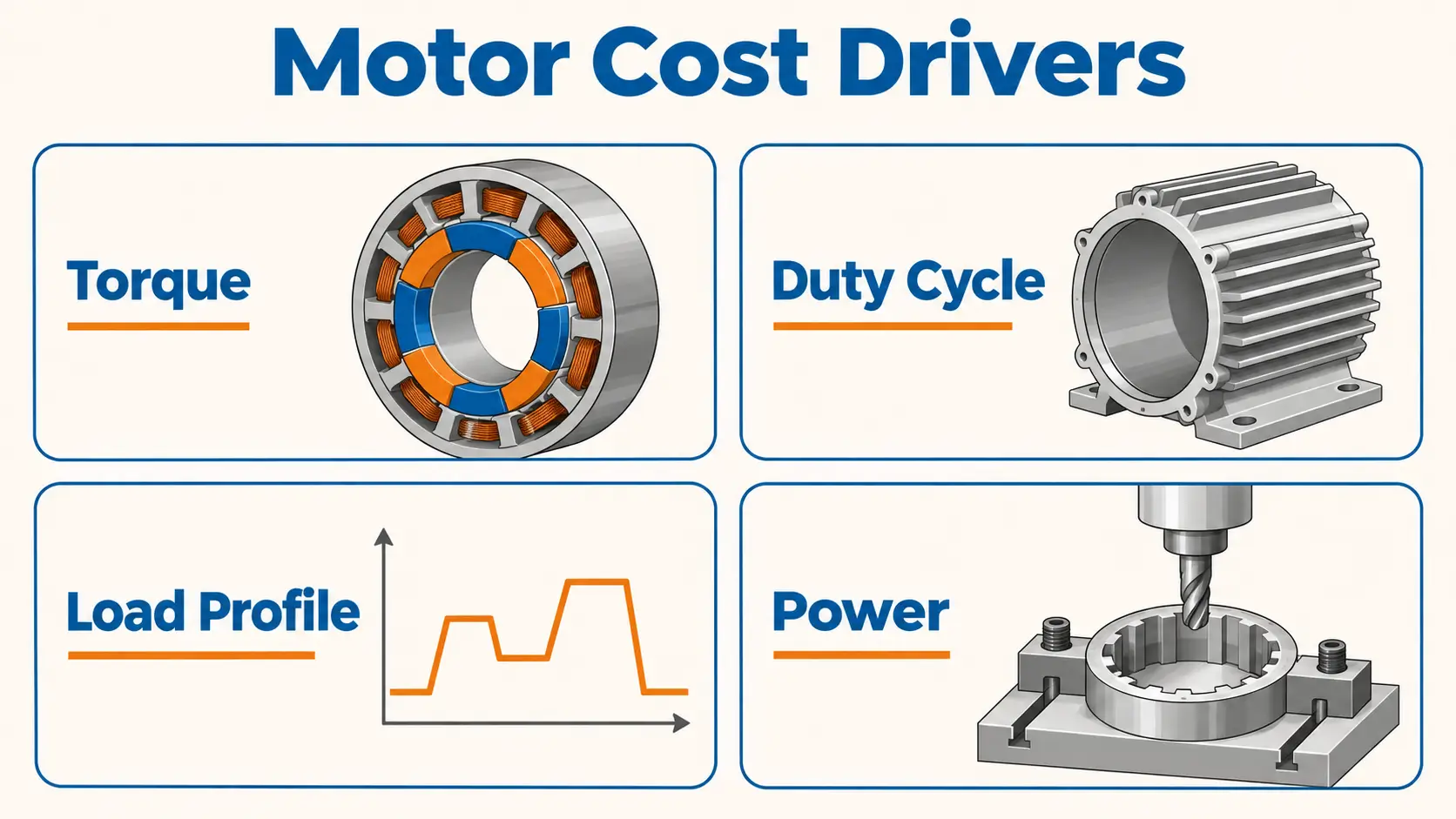
Two machines rated at the exact same nominal power can demand completely different magnet mass, copper slot fill, frame cooling, and bearing load ratings depending on their torque duty cycle. Because accurate motor engineering always starts from the driven machine rather than a catalog table, buyers can review our methodology for choosing the right PMSM motor for different applications to see how machine operating conditions translate into motor design parameters.
Similarly, because regional grid tolerances, local compliance rules, and operating environments directly impact motor specification, much like the regional engineering criteria detailed in our project selection guide for Singapore industrial applications, providing target market compliance requirements upfront allows our team to select the correct insulation, efficiency baseline, and documentation scope from day one.
In our quotation workflow, we clearly separate parameters that must be defined by your machine engineering team from internal motor design variables that our engineers calculate and propose for your approval. Host machine boundary conditions such as load torque curves, duty cycle, supply voltage, mounting envelope limits, existing VFD hardware, and annual batch volume must come from your application data.
Internal motor parameters such as slot pole combination, permanent magnet grade and thickness, winding turn configuration, and recommended cooling structure are engineered by our team and submitted for your written sign off. When an inquiry contains descriptive phrases like high efficiency, quiet operation, or heavy duty reliability, our engineers work with your team to convert them into measurable test conditions specifying exact load points, speed ranges, measurement standards, and pass/fail acceptance thresholds.
| Requirement Category | Engineering Inputs We Review | Manufacturing & Pricing Impact When Omitted |
|---|---|---|
| Performance & Load Profile | Load type, continuous/peak torque, speed range, duty cycle (S1 to S9), start/stop frequency, load inertia. | Forces a default continuous S1 nominal assumption, risking either thermal demagnetization under peak loads or an oversized, overpriced frame. |
| Electrical Supply | Rated voltage, phase count, supply frequency, allowable voltage fluctuation, insulation and dielectric requirements. | Winding back EMF may exceed VFD voltage ceilings at high speed or fail to deliver rated torque during plant voltage sags. |
| Mechanical & Mounting | Frame size limits, mounting arrangement (B3/B5/B35), shaft diameter/length/keyway, radial/axial loads, terminal box position. | Pricing defaults to standard catalog castings; late discovery of envelope interference triggers new tooling costs and schedule delays. |
| Environmental & Cooling | Ambient temperature range, altitude, humidity, corrosive/dust exposure, target IP rating, cooling method (IC411/IC416/liquid). | Standard IP54/IP55 and IC411 cooling are assumed, which can lead to seal, bearing, or insulation failure in harsh environments. |
| Drive & Control Interface | Existing VFD/servo drive brand and model, control mode (FOC/sensorless), encoder/resolver type, communication protocol. | Motor inductance, pole count, or feedback signals may conflict with the drive, causing commissioning failure or harmonic overheating. |
| Quality, Volume & Commercial | Prototype vs batch volume, delivery schedule, routine vs type test scope, required documentation, packaging, Incoterms. | NRE amortization, magnet MOQ constraints, and dynamometer test costs cannot be allocated accurately into the unit price. |
Load, Torque and Duty Cycle Inputs
In our electromagnetic calculation workflow, your load classification, torque curve, speed range, and duty cycle determine how we size the stator core, select the permanent magnet grade, and calculate thermal rise. Constant torque loads (such as extruders, conveyors, and positive displacement pumps), constant power loads (such as winders and machine tool spindles), variable torque squared loads (such as centrifugal fans and pumps), and cyclical impact loads (such as presses and injection molding machines) impose completely different thermal and demagnetization stresses on the motor.
For low speed constant torque drives, our design focuses on low speed heat dissipation and breakaway starting torque. For cyclical impact loads, we must calculate peak stator current density during overload bursts and verify that the permanent magnets maintain a safe coercivity margin against irreversible demagnetization at peak operating temperature. Providing only a nominal kilowatt rating hides these critical transient stresses.
Our engineers evaluate your operating speed range, duty cycle, and start stop frequency as a single coupled thermal system. The ratio between base speed and maximum speed dictates whether the motor enters a flux weakening zone, which directly governs our winding inductance design and VFD current sizing.
At the same time, the duty cycle profile (such as continuous S1 duty versus intermittent periodic duty with defined on load, off load, and de energized intervals) and hourly start/stop/reversing frequency determine the root mean square (RMS) thermal load inside the stator slots.
A motor running at a 25% intermittent duty cycle with high inertia acceleration ramps requires a fundamentally different electromagnetic and mechanical design than a motor running continuously at steady speed.
Providing the following five load and duty cycle parameters in your initial inquiry allows our engineering team to size the active materials accurately without padding the frame size.
- Load Classification & Torque Speed Curve Specify whether the driven machine follows a constant torque, constant power, variable torque, or cyclical impact profile across the speed range so we can align the efficiency and torque envelope.
- Continuous and Peak Torque with Duration State required continuous torque (Tn), maximum peak overload torque (Tmax), and exact duration in seconds per cycle so we can calculate magnet demagnetization margins and copper slot fill.
- Base Speed, Minimum Speed, and Maximum Speed Define the full continuous speed regulation range and any constant power flux weakening zone so we can verify back EMF limits and bearing/cooling performance at speed extremes.
- Duty Cycle Profile and Start/Stop Frequency Provide the IEC duty type (or time series load diagram) and hourly start/stop cycles so we calculate true RMS thermal equilibrium rather than defaulting to an S1 continuous assumption.
- Load Moment of Inertia (Jload) and Ramp Times State reflected load inertia at the motor shaft and required acceleration/deceleration times so we can verify dynamic torque margins and rotor to load inertia matching.
Supply, Drive and Control Requirements
We treat your electrical supply parameters and existing drive hardware as non negotiable boundary constraints during winding design. Because an inverter driven PMSM relies on electronic commutation while its permanent magnet rotor generates a continuous back EMF proportional to rotational speed, our winding turn count must be engineered around your exact AC supply voltage, phase configuration, input frequency, and voltage sag limits.
If a custom motor must operate with an existing VFD or servo drive in your facility or OEM cabinet, we need the drive brand, model, continuous and peak output current ratings, switching frequency range, and supported PM control modes before we freeze the electromagnetic design. Designing a PMSM without knowing the drive’s voltage and current ceilings risks over voltage trips during high speed coasting, current saturation during acceleration, or costly winding changes after sample testing.
Our engineering team also aligns feedback sensors, thermal protection, and commissioning parameters directly with your control architecture. If your PLC or motion controller requires a locked feedback interface such as an incremental encoder with specific pulse counts, a multi turn absolute encoder using EnDat, BiSS C, or SSI protocols, or a resolver alongside PT100, PTC, or KTY84 stator temperature sensors, we integrate those exact components into the rear endbell design and wiring harness.
If your drive supports multiple feedback options or sensorless vector control, tell us your target speed or position control accuracy and our engineers will recommend a proven, cost effective sensor configuration. We also confirm upfront whether your team requires measured motor equivalent circuit parameters for drive auto tuning.
Sharing the following six electrical and drive parameters allows our engineers to guarantee motor drive compatibility before sample fabrication.
- Supply Voltage, Frequency, and Fluctuation Tolerance Nominal AC input voltage, phases, frequency, and percentage voltage tolerance so we leave sufficient winding voltage margin under low line conditions.
- Existing VFD/Servo Drive Brand, Model, and Current Limits Exact drive hardware and continuous/overload output current ratings so we match motor rated current and inductance to your inverter capacity.
- Control Mode Requirements Whether the drive runs sensorless vector control, closed loop FOC, torque control, or position control so we optimize rotor saliency and inductance ratios.
- Feedback Sensor Type, Resolution, and Supply Voltage Required encoder or resolver specification, mechanical mounting style, signal voltage, and cable shielding requirements.
- Thermal Sensor and Holding Brake Integration Stator winding thermal sensor type (PTC/PT100/KTY) and holding brake voltage and static torque requirements if applicable.
- Commissioning Parameter Delivery Confirmation of measured equivalent circuit parameters (Rs, Ld, Lq, Ke, rotor inertia, pole pairs) required on our sample test sheet for your VFD setup.
How Our Engineering and Quality Systems Support Supplier Audits?
Experienced procurement and engineering leads auditing Chinese custom PMSM manufacturers look past company size or brochure claims and examine three operational systems including how the engineering team reviews design inputs and states assumptions, how the quality system links material batch traceability to product level test reports, and how Engineering Change Notices (ECN) lock version consistency from prototype to mass production.
Generic marketing claims such as decades of experience or strict quality control mean nothing unless backed by auditable process records, calculation sheets, and serial numbered test data. Likewise, a factory’s ISO system certificate or a standard series product mark applies only to its stated scope and cannot be assumed to cover a modified custom variant without specific verification.
While China has a broad base of motor factories serving pumps, fans, compressors, and industrial machinery, buyers building a supplier shortlist can review how we benchmark permanent magnet synchronous motor manufacturers in China for general specification verification, and then audit Hiest’s custom engineering and quality workflows against the three pillars below.
In our factory operations, every capability claim is tied to a specific engineering role, a calculation or test standard, and a written record. When we evaluate a custom project, our engineers generate a design input review sheet, electromagnetic calculation outputs, and a preliminary outline drawing for customer confirmation.
On the compliance side, we verify the exact frame scope, temperature class, and validity status of any required certification upfront, because modifying housing geometry, cooling topology, or insulation systems on a custom motor frequently requires a formal certification extension or dedicated type testing rather than relying on standard catalog certificates.
Engineering Response and Design Input Review
When our engineering team receives your custom inquiry, our first deliverable is a structured design input review rather than an unverified price number. We audit your operating parameters, flag any missing load spectrum, duty cycle, thermal, or mounting constraints, and explicitly state every boundary assumption used to generate our preliminary calculation.
Because a permanent magnet synchronous motor is only the right commercial choice when documented efficiency, compact footprint, or variable speed control justifies its installed system cost over a traditional asynchronous motor, our engineers also help you evaluate whether a PMSM or an induction motor fits your industrial project objectively, separating proven platform test data from new design estimates.
By contrast, when a supplier returns an instant price quote on an incomplete custom inquiry without asking a single technical question or stating any thermal or VFD assumptions, technical risks are simply hidden until prototype failure. Skipping speed range or drive matching checks during initial quoting inevitably triggers rework once metal is cut.
In our engineering workflow, we document our assumed duty cycle, ambient temperature, cooling condition, magnet temperature grade, and VFD voltage ceiling directly on our technical proposal sheet, and we require a formal outline drawing and specification sign off before releasing manufacturing drawings to the shop floor.
| Review Dimension | Hiest Engineering Review Standard | Risk of Unverified Quoting | Deliverable Provided to Buyer |
|---|---|---|---|
| Handling of Input Gaps | We identify missing duty cycle, inertia, VFD current, or mounting tolerances before locking the electromagnetic design. | Quoting blindly on incomplete parameters leads to undersized thermal margins or mechanical interference at assembly. | Itemized technical clarification list defining inputs needed to move from budget estimate to frozen design. |
| Declaration of Assumptions | We explicitly label assumed cooling conditions, magnet temperature limits, and efficiency test baselines in our proposal. | Unconditional performance claims without stated test conditions or VFD settings cannot be reproduced on your test rig. | Written boundary assumption table attached to the torque, speed, and efficiency calculation summary. |
| Design Review Outputs | We provide preliminary 2D/3D outline drawings, calculated performance curves, and a defined prototype test plan. | Relying on a generic catalog table or single line price quote leaves interface and acceptance criteria undefined. | Preliminary technical specification sheet and outline drawing sign off gate prior to prototype fabrication. |
Quality Documentation, Testing Scope and Traceability
To give procurement and quality teams clear verification boundaries, Hiest separates quality documentation into three distinct tiers including quality management system (QMS) procedures, batch production inspection records, and product level dynamometer test reports. Each document serves a specific purpose and has strict non extrapolation boundaries.
Our system level documentation governs document control, gauge calibration, and process routing; our batch inspection records verify that incoming raw materials and 100% outgoing routine electrical checks meet tolerance on a specific production lot; and our product level type test reports record how a specific motor serial number performed under controlled laboratory load, speed, and thermal conditions. We never extrapolate a standard model test report to represent an untested custom design, and every test report we issue states the motor model, serial number, winding specification, test standard version, cooling setup, drive configuration, and test date.
On our production line, batch traceability links critical raw materials and key in process manufacturing steps directly to the finished motor serial number. Sustaining consistent electromagnetic and mechanical performance across custom production batches requires tracking permanent magnet grade and batch coercive force certificates, electrical steel lamination lot numbers, magnet wire insulation ratings, vacuum pressure impregnation (VPI) process logs, rotor dynamic balance records, and 100% routine outgoing electrical tests (covering winding resistance, insulation resistance, dielectric withstand voltage, and no load back EMF constant). Linking serial numbers to material lots and process records ensures that repeat orders match the approved sample baseline and allows rapid root cause isolation if a field issue ever arises.
| Evidence Tier | What Our Documentation Proves | Scope Limitations & Non Extrapolation Boundaries | How Buyers Verify This With Us |
|---|---|---|---|
| System Level Documentation | Existence of quality management procedures, instrument calibration schedules, and document control frameworks. | Does not prove electromagnetic accuracy, thermal margin, or compliance of a specific custom motor design. | Review certificate validity scope and how custom engineering orders are routed through our QMS. |
| Batch Inspection & Traceability Records | Consistency of incoming magnet/steel batches, in process winding/balance checks, and 100% routine electrical tests. | Routine no load and hi pot tests do not verify full load thermal rise, efficiency map, or peak overload torque. | Request sample routine test sheets showing serial number linkage to magnet batch and winding parameters. |
| Product Level Type Test Reports | Verified performance (torque, speed, efficiency, temperature rise) of a specific sample under stated test conditions. | Valid only for the tested model configuration, cooling setup, and VFD pairing; cannot be generalized to other ratings. | Confirm dynamometer test conditions, measurement standards, and whether figures reflect calculated vs measured data. |
Change Control and Version Management for Custom Designs
In custom motor manufacturing, strict version management and Engineering Change Notice (ECN) control are the only mechanisms that guarantee your tenth production batch matches your approved prototype. Because custom PMSM development often involves refinements during prototype testing such as adjusting winding turns by a few percent, tightening a flange pilot tolerance, or changing a connector orientation, every modification in our factory must pass through a five step ECN workflow including written change request initiation, cross functional impact review (covering electromagnetic performance, mechanical fit, tooling, unit cost, and lead time), formal written customer sign off, drawing and BOM version incrementation, and synchronized updates to shop floor work instructions and outgoing inspection standards.
Without formal ECN control, verbal or email adjustments agreed upon during sample debugging frequently fail to reach the production purchasing or assembly teams, resulting in mass production units that revert to old shaft dimensions or use unapproved sub supplier components. To give buyers complete transparency into how we lock custom designs, our engineering and quality teams establish three version control commitments on custom projects.
- We bind drawing revision numbers, stator winding specifications, and locked BOM versions directly to your custom part number and nameplate serialization across prototype and batch runs.
- We require formal written customer approval on an Engineering Change Notice before any modification to critical dimensions, winding parameters, or locked BOM grades is released to production.
- If a critical raw material batch or specified sub supplier component (such as permanent magnets, bearings, or feedback sensors) ever requires an alternative source, we execute a formal notification and re validation protocol prior to batch assembly.
How We Execute Custom PMSM Development from Prototype to Production Release?
At Hiest, custom PMSM development moves through four controlled stage gates including requirement review and scheme confirmation, prototype design and fabrication, sample testing and customer sign off, and mass production preparation with batch release verification. At each gate, our engineering team delivers specific, auditable outputs for your confirmation.
In our manufacturing process, customer sample sign off is not treated as the end of engineering; it is the baseline gate where we translate single unit prototype validation into frozen batch tooling, shop floor control plans, and outgoing inspection bands. Note that while this four phase structure reflects our standard industrial project workflow, exact stage gate forms, prototype lead times, and sample fee structures are confirmed per project based on your customization tier.
Rather than treating sample fabrication and volume production as identical processes, our engineering team explicitly manages the physical transition between soft tooled prototypes and hard tooled batch manufacturing. Because initial prototypes are frequently built in single unit or small lot quantities using soft tooling methods to save time and upfront die investment, passing a bench test on a prototype only guarantees batch consistency if tooling transitions and routine inspection limits are formally locked before mass production begins.
| Development Phase | Required Project Inputs | Outputs We Deliver | Joint Confirmation Gate |
|---|---|---|---|
| Requirement Review & Scheme Confirmation | Six category application inputs, envelope drawings, drive specs, target volume. | Preliminary electromagnetic calculation, outline & interface drawing, assumption list, NRE/unit quote. | Written sign off on frozen baseline specification, outline drawing revision, and prototype test plan. |
| Prototype Design & Build | Approved specification baseline, signed outline drawing, agreed test criteria. | Detailed manufacturing drawings, prototype BOM, record of prototype build method (soft vs hard tooling). | Confirmation of any in build adjustments and verification of material certificates (magnets, laminations, sensors). |
| Sample Testing & Customer Sign Off | Fabricated prototype units, calibrated dynamometer test rig, target VFD/controller. | Serial numbered type test report, dimensional inspection sheet, measured motor parameter sheet. | Formal sample approval sign off coupled with ECN resolution for any performance or fit refinements. |
| Mass Production Prep & Release | Signed sample approval, finalized BOM/drawings, batch order schedule. | Production tooling/fixture readiness record, control plan, routine vs sampling inspection protocol. | Written production release authorization after verifying batch inspection criteria and tooling transition. |
From Design Review to Prototype Build
Before our shop floor starts fabricating a custom prototype, our engineering team works with you to freeze five baseline items including the specification baseline and document version number, the electromagnetic magnetic circuit and winding scheme, the 2D/3D mechanical outline and mounting tolerances, the VFD and controller matching assumptions, and the prototype test plan with pass/fail criteria. Locking these five items via signed outline drawings and a confirmed specification sheet ensures that prototype fabrication tests a known engineering baseline rather than a moving target. If any boundary parameter remains unconfirmed during build, it becomes impossible to isolate whether a test deviation stems from electromagnetic calculation, machining tolerances, or drive parameter settings.
We also document the exact fabrication method used to build your prototypes so your engineering team can interpret test data accurately. In custom motor development, initial prototypes are often fabricated using laser cut electrical steel laminations instead of progressive stamping dies, CNC machined aluminum or cast iron housings instead of production casting molds, and manual coil winding instead of automated winding machines. Soft tooled prototypes are an effective way to verify torque speed curves, thermal equilibrium, and mechanical fit without committing full die investment upfront. However, because laser cut laminations can exhibit slightly different edge burr and iron loss characteristics than stamped laminations, and manual winding can differ in slot fill factor from automated winders, we record the prototype build method on the test sheet and account for any tooling transition effects before releasing mass production.
If any specification detail such as a shaft tolerance, winding turn count, magnet grade, or encoder model needs to be adjusted during prototype build due to updated customer requirements or component lead times, our engineers log a formal revision before dynamometer testing begins. Maintaining strict revision records during the prototype build ensures that physical test results correlate directly with our electromagnetic simulation baseline and final production BOM.
Sample Testing, Acceptance and Production Release
Once prototype assembly is complete, our laboratory executes sample testing against the exact test items, measurement standards, and operating conditions agreed upon during design review, generating a serial numbered test record for your sign off. A complete prototype verification package combines a dimensional inspection sheet (checking mounting pilot diameters, shaft runout, keyway tolerances, and overall envelope) with routine electrical checks (winding resistance, insulation resistance, dielectric withstand voltage, and no load back EMF waveform) and load performance verification (efficiency, power factor, stator temperature rise at rated duty, and peak torque capability). The specific test items, applicable standards, and acceptance thresholds for your project are confirmed against our laboratory test rig capabilities and your contract scope.
When you test our samples on your machine, formal sample sign off serves to lock the frozen technical specification, outgoing batch acceptance criteria, ECN rules, and quality responsibilities. If your field trials show that a minor refinement is needed such as shifting the back EMF constant by 5% to better match your VFD voltage ceiling, relocating a terminal box entry, or adjusting shaft keyway length, our engineering team documents the adjustment under an ECN and confirms with you whether the change requires a second sample verification loop or can be verified through first article inspection (FAI) at the start of batch production.
Most importantly, our production system never treats single unit sample approval as an automatic release for unmonitored volume production. Moving from a prototype build to batch production introduces lot to lot tolerances in permanent magnet flux density, stamping die wear, automated winding tension, varnish impregnation uniformity, and assembly fixture alignment. Prior to releasing a batch order to the shop floor, we translate the approved prototype test results into a production control plan that confirms hard tooling and fixture readiness, locks 100% outgoing routine test tolerance bands (such as allowable back EMF and winding resistance ranges), and defines batch sampling rules for load and thermal checks.
How We Calculate Cost, MOQ and Lead Time for a Custom PMSM Order?
In custom motor manufacturing, a Hiest commercial quotation is built from two distinct cost structures consisting of one time Non Recurring Engineering (NRE) development investments and recurring unit manufacturing costs. One time NRE covers electromagnetic and structural design, custom stamping dies, casting molds, machining and winding fixtures, prototype fabrication, and type testing. Recurring unit cost is governed by active electromagnetic material mass and grade (specifically rare earth permanent magnets, electrical steel, and copper winding wire), housing and shaft machining complexity, feedback sensor specification, order batch size, and required testing and packaging scope. When buyers see large price gaps between different Chinese suppliers, it is almost always because one quote bundles NRE, full load testing, or high temperature magnets while another omits them or assumes a different duty cycle.
Our Minimum Order Quantity (MOQ) and delivery lead time are similarly dictated by physical supply chain and shop floor constraints rather than arbitrary sales rules. MOQ is set by raw material sub supplier batch minimums (such as custom sintered NdFeB magnet blocks or specialized shaft forgings), automated line changeover labor, and tooling amortization economics. Lead time is determined by the sequential critical path of engineering drawing sign off, prototype fabrication, sample testing and customer approval, long lead raw material procurement, and shop floor production scheduling. Because unit price, MOQ, and lead time are directly linked, our quotations state all three variables together alongside the exact technical and testing scope included.
| Commercial Variable | Primary Factory Cost & Schedule Drivers | Where We Can Offer Commercial Flexibility | Physical & Supply Chain Hard Constraints |
|---|---|---|---|
| One Time Development Cost (NRE) | Number of custom dimensions, new lamination stamping dies, casting molds, winding fixtures, prototype count, type test scope. | Amortizing NRE over a committed annual volume contract or using soft tooling (laser cutting/CNC) for initial prototype validation. | Physical die/mold fabrication costs and dynamometer setup labor when geometry falls outside existing platforms. |
| Recurring Unit Cost | Rare earth magnet grade/mass (e.g., NdFeB temperature class), silicon steel grade, copper slot fill, encoder brand, batch size. | Optimizing batch release quantities, proposing validated alternative sensor brands, and aligning packaging and Incoterms scope. | Active electromagnetic material mass (magnet/copper/steel) required to meet locked torque and thermal rise physics. |
| Minimum Order Quantity (MOQ) | Sub supplier MOQs for custom magnets, special bearings, custom extrusions/castings, and automated line changeover setup. | Sharing existing stator/rotor laminations, structuring blanket orders with scheduled split deliveries, or price tiered pilot batches. | Sintering furnace and mill batch minimums for non standard magnet arc geometries or specialized alloy shafts. |
| Lead Time | Engineering review complexity, soft/hard tooling lead time, prototype test duration, long lead component sourcing, plant queue. | Pre booking long lead magnets/sensors under blanket forecasts, partial air shipments, and parallel drawing review gates. | VPI varnish curing cycles, thermal equilibrium test duration, and custom magnet/encoder sub supplier lead times. |
One Time Development Cost vs Unit Cost
When we prepare a custom quotation, we separate one time development expenses (NRE) into four transparent categories covering electromagnetic and 3D/2D structural engineering, dedicated tooling and fixtures (stator/rotor stamping dies, housing casting molds, shaft machining fixtures, and winding tooling), prototype material sourcing and small lot build labor, and laboratory type testing or third party certification fees. NRE scales directly with how far your design departs from our existing platforms; a modified shaft extension or custom flange adapter requires only simple machining fixtures, whereas a custom stator outer diameter requires dedicated stamping dies or laser cut sample setups.
How NRE is structured commercially has a direct impact on your unit price. If you prefer to pay NRE as a separate upfront milestone item, your recurring unit price reflects only active materials, machining, assembly, routine testing, and factory overhead. If you prefer to amortize NRE into the unit price over an agreed order quantity, the per unit amortization drops as batch volume increases. Meanwhile, the baseline recurring unit cost is driven by physical material specifications such as high coercivity permanent magnet grades needed to prevent high temperature demagnetization, low loss electrical steel laminations for high frequency efficiency, high resolution absolute encoders, and liquid cooled housing machining. Because changing batch sizes or splitting deliveries alters both material purchasing tiers and NRE amortization math, every unit price we quote is tied to a stated volume baseline.
To give your procurement team complete cost transparency, our quotations follow three standard cost breakdown practices.
- We itemize one time NRE charges (separating engineering, tooling/molds, prototype units, and type testing) completely apart from recurring mass production unit pricing.
- We state the exact annual and per batch order quantities, permanent magnet temperature class, insulation class, feedback sensor model, and included outgoing test scope in the recurring unit price.
- We define commercial terms for dedicated tooling ownership, maintenance, and NRE amortization or rebate thresholds when cumulative order volumes reach agreed targets.
MOQ and Lead Time Conditions
In our supply chain and production planning, Minimum Order Quantity (MOQ) is governed by three practical factors including raw material sub supplier minimums, shop floor setup and changeover economics, and component commonality with our active production lines. When a custom motor requires non stock permanent magnet arc dimensions, specialized high temperature NdFeB grades, custom extruded aluminum housings, or imported brand specific encoders, our purchasing team must meet the minimum batch quantities required by magnet sintering plants, foundries, and sensor distributors. On the shop floor, setting up automated stator winders, CNC lathes, and dynamometer fixtures for a custom run carries fixed setup labor. However, when we engineer your custom motor as an adaptation of an existing lamination platform that shares standard bearings and housing castings with our regular production, we can significantly lower the initial pilot batch MOQ or structure a blanket contract with scheduled split releases.
Our project lead time is built across five sequential stages including engineering design review and outline drawing sign off, prototype tooling and sample fabrication, sample testing and customer approval, long lead raw material procurement for volume production, and batch machining, winding, assembly, routine testing, and export packaging. In custom PMSM orders, the critical path is almost always determined by completing the sample verification loop and procuring custom sintered magnets, castings, or specified encoders once the BOM is frozen. Because raw materials for custom dimensions cannot be ordered in volume until the prototype design is signed off, any delay in confirming interface drawings or VFD parameters shifts the downstream delivery date day for day.
We work closely with buyers to optimize both MOQ and lead time through production planning. Committing to an annual forecast with a frozen technical specification allows our supply chain team to pre book long lead magnets and laminations, cutting repeat order lead times down to machining, winding, assembly, and routine testing. Conversely, ordering frequent small unscheduled batches without material forecasts increases line changeover frequency and per batch testing overhead. We therefore state the exact batch size, material stocking arrangement, and drawing sign off milestones behind every MOQ and lead time commitment in our quotation.
How We Prevent Post Order Manufacturing and Integration Risks?
Experienced buyers know that in custom motor sourcing, the most expensive commercial and technical failures occur after the purchase order is placed, between detailed drafting, sample approval, and batch delivery. Post order failures rarely happen by accident; they occur when initial quotations are built on unstated assumptions, when material substitutions bypass engineering review, when soft tooled prototypes transition poorly to hard production tooling, or when motor back EMF conflicts with the field VFD during site commissioning. Below is how the engineering, quality, and production teams at Hiest lock down the six primary post order risk areas before batch manufacturing begins.
While no industrial manufacturing process can eliminate physical tolerance variables entirely, our stage gate workflow converts each post order risk into a binding pre production verification gate between our engineering team and yours.
- Preventing Specification Drift from Unstated Assumptions
Where Projects Fail A sales quote is issued on nominal power and speed alone while thermal duty cycle, shaft radial load, or ambient altitude remain unstated, causing mechanical or thermal conflicts once detailed drafting starts.
Our Factory Control Gate We lock a six category technical specification sheet and signed 2D/3D outline drawing (specifying pilot tolerances, shaft runout, and thermal class) as a binding technical appendix prior to cutting prototype metal. - Preventing Uncontrolled Material or Component Substitution
Where Projects Fail During volume production, a factory substitutes a lower coercivity magnet grade, an unapproved bearing brand, or a different thermal sensor to cut costs or bypass shortages, reducing thermal demagnetization margins or bearing life.
Our Factory Control Gate We establish a locked Critical BOM in your contract specifying approved permanent magnet temperature grades, insulation classes, bearing brands, and sensor models, governed by a mandatory written ECN sign off rule. - Preventing Prototype to Batch Performance Drift
Where Projects Fail Hand built prototypes using CNC housings and laser cut laminations pass bench testing, but mass production units built on stamped dies and automated winders show shifted back EMF constants, higher cogging torque, or fit deviations.
Our Factory Control Gate We record prototype build methods upfront, execute a formal First Article Inspection (FAI) when transitioning to hard production tooling, and lock 100% outgoing routine test tolerance bands (including back EMF and winding resistance limits) to the approved sample baseline. - Preventing Field VFD and Control Loop Mismatches
Where Projects Fail A custom PMSM runs smoothly on a factory laboratory inverter but trips on over current, fails sensorless startup, or overheats from harmonic losses when wired to the customer’s field VFD.
Our Factory Control Gate Our engineers verify back EMF ceilings and stator inductance against your exact field VFD model before design freeze, and we deliver measured Rs, Ld, Lq, and Ke parameters with the prototype test report to streamline your commissioning. - Preventing Compliance and Documentation Gaps
Where Projects Fail Buyers assume a custom motor automatically inherits standard catalog CE, UL, efficiency class, or explosion proof certificates, only to find during customs clearance or site audit that the custom rating falls outside the certificate scope.
Our Factory Control Gate We verify the exact model scope, frame coverage, and validity dates of all required certificates before order confirmation, and we list the exact test reports, material certificates, and compliance declarations in the order contract. - Preventing Critical Path Lead Time Slippage
Where Projects Fail Lead time is quoted as a single lump sum week number without accounting for custom magnet sintering queues, laboratory dynamometer scheduling, or drawing revision loops, delaying the customer’s machine build.
Our Factory Control Gate We provide a milestone schedule breaking out drawing sign off, long lead material arrival, prototype build, sample testing, and batch assembly, clearly defining that production lead time starts upon final technical drawing sign off.
How to Structure Your RFQ Package for an Apples to Apples Quotation?
From a manufacturer’s perspective, the fastest way to get an accurate, buildable price and a firm delivery schedule is to submit an RFQ structured around nine complete engineering and commercial inputs covering application and load characteristics, performance and speed range targets, electrical supply and drive conditions, mechanical mounting and interface drawings, environmental and ingress protection requirements, prototype and batch quantities with delivery schedules, testing and acceptance criteria, required documentation deliverables, and ECN change management rules. When comparing a Hiest proposal against other Chinese suppliers, we encourage your engineering and procurement teams to audit each response line by line to see which technical conditions are explicitly confirmed, which rely on provisional assumptions, and which were skipped, rather than comparing bottom line unit prices in isolation.
Whenever two factories quote against different underlying assumptions, for instance if our quotation includes high temperature NdFeB magnets rated for continuous S1 thermal equilibrium and 100% routine back EMF verification while another quote assumes intermittent duty with lower grade magnets and basic no load checks, the two unit prices represent completely different physical motors. Submitting a standardized Technical Data Package forces every supplier to price the exact same engineering scope, making technical capability gaps and hidden commercial exclusions visible before you commit sample budget.
Technical Data Package and Acceptance Criteria
When submitting an RFQ to our engineering team, organizing your Technical Data Package (TDP) into the five files below allows us to complete our platform fit analysis, electromagnetic calculation, and NRE/unit cost breakdown without guesswork.
- Application and Load Profile Sheet Driven machine type, load classification, continuous and peak torque values, overload duration, reflected load inertia, and a time series duty cycle or start/stop frequency log so we size thermal and magnet margins accurately.
- Performance and Speed Range Target Specification Rated power, base speed, minimum and maximum continuous speed, constant power flux weakening range, and target efficiency conditions with stated test baselines.
- Electrical and Drive Interface Definition Nominal supply voltage, voltage tolerance, VFD/servo drive brand, model, continuous/peak current ratings, switching frequency, control mode, feedback sensor protocol, and thermal sensor wiring.
- Mechanical Interface Drawings and Envelope Constraints 2D/3D outline drawings specifying mounting type (B3/B5/B35), flange pilot tolerances, shaft diameter, length, keyway/spline geometry, radial/axial bearing loads, and terminal box or cable exit orientations.
- Environmental, Cooling, and Compliance Requirements Ambient temperature range, altitude, humidity/corrosive exposure, target IP rating, cooling method (with flow rate, inlet temperature, and pressure limits if liquid cooled), and required certification scopes.
To eliminate any ambiguity during sample sign off and batch inspection, our engineering team structures acceptance criteria using a strict three part format combining Measurable Parameter + Defined Test Condition + Pass/Fail Evaluation Method. In our technical proposals, we clearly separate parameters verified during prototype dynamometer type testing (such as full load thermal equilibrium, efficiency mapping, and peak torque capability under relevant IEC or GB/T standards) from parameters verified on 100% of batch units during outgoing routine testing (such as winding resistance balance, insulation resistance, dielectric hi pot withstand, and no load back EMF constant). For every line item in your RFQ specification, our engineers mark our response explicitly as Confirmed, Conditional/Assumed (with the exact condition stated), or Exception/Alternative Proposed.
Your engineering and procurement teams can use the verification matrix below to audit our proposal alongside other supplier responses and determine the right next step for your project.
| Proposal Audit Dimension | What to Verify Across Competing Quotations | Recommended Project Decision Gate |
|---|---|---|
| Technical Scope Alignment | Did the manufacturer confirm all five TDP input files (torque/duty cycle, speed range, VFD limits, mechanical drawings, cooling/IP) and state whether the quote is a platform adaptation or a redesign? | Advance to Prototype Build when core operating inputs are confirmed and the customization tier and tooling scope are explicitly stated. |
| Transparency of Engineering Assumptions | Are all engineering assumptions (magnet temperature class, assumed VFD switching frequency, cooling air velocity, and soft vs hard prototype tooling) explicitly documented and aligned with your machine? | Hold Commercial Comparison & Align Baseline if assumptions conflict with your machine conditions or if critical operating parameters were left unconfirmed. |
| Commercial & Acceptance Breakdown | Does the quotation separate one time NRE from recurring unit cost, state the exact batch volume and MOQ baseline, and confirm the three part acceptance test criteria and ECN rules? | Reject Unverified Quotes when a supplier refuses to disclose design assumptions, conflates no load checks with full load testing, or ignores VFD voltage/current ceilings. |
Conclusion
From a custom PMSM manufacturer’s perspective, delivering a reliable motor at an accurate commercial price depends on locking the technical baseline before metal is cut. Because company names, standard catalog pages, and unstandardized unit prices cannot prove custom engineering execution, every successful project begins by translating your machine’s actual load torque, speed range, duty cycle, electrical supply, VFD limits, mechanical envelope, and environmental conditions into a unified specification baseline. When candidate suppliers are required to respond to that baseline with explicit customization tiers, transparent boundary assumptions, itemized NRE and unit costs, and traceable testing and ECN commitments, procurement and engineering teams can evaluate proposals on verifiable manufacturing facts rather than sales promises.
When you are ready to evaluate custom PMSM feasibility or request a formal engineering quotation from Hiest, we recommend following this six step project sequence.
- Share Your Six Category Operating Baseline Provide your load torque curve, duty cycle, speed range, VFD hardware model and current limits, mechanical interface drawings, and cooling/IP requirements so our engineers can evaluate your true operating point.
- Review Our Platform Adaptation vs Redesign Assessment Let our engineering team confirm whether your requirements fit within an existing lamination platform adaptation or require a dedicated electromagnetic and structural redesign.
- Confirm Boundary Assumptions and Outline Drawings Review our preliminary technical proposal sheet, stated thermal and drive assumptions, and 2D/3D outline drawings before authorizing prototype fabrication.
- Align on Itemized NRE, Unit Cost, MOQ, and Lead Time Review our separated breakdown of one time NRE tooling/testing charges versus recurring unit prices alongside the stated batch volume and material lead time assumptions.
- Lock Three Part Acceptance Criteria Confirm the exact prototype dynamometer type tests and 100% outgoing batch routine tests (including back EMF and hi pot tolerance bands) prior to sample build.
- Execute Formal Sample Sign Off and Production Release Verify prototype test reports, measured VFD motor parameters, locked Critical BOM grades, and hard tooling readiness with our team before releasing volume production.
If certain machine load points or drive parameters are still under development on your side, share your current boundary estimates with our engineering team first so we can identify the critical variables together before locking a commercial quote. All model specific parameters, platform coverage limits, certifications, test rig capacities, unit prices, MOQs, and delivery schedules are confirmed formally in writing against your project drawings and engineering review.