
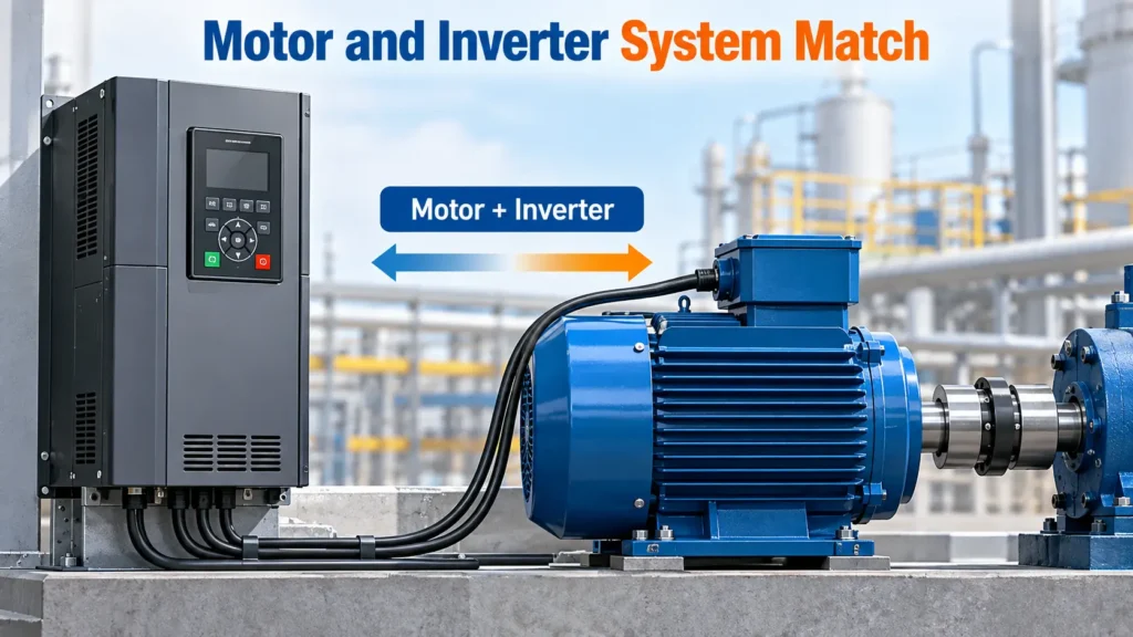
Can an existing variable frequency drive operate a replacement permanent magnet synchronous motor without upgrading the drive? The answer depends on verified PM motor control support, available output voltage and current, application torque requirements, motor parameters, feedback configuration, and system-level protection. Matching horsepower or rated voltage alone does not establish PMSM VFD compatibility.
A VFD that has operated an induction motor reliably may not support the control characteristics of a replacement PMSM. Even when permanent magnet motor control is available, the drive must have sufficient capacity and suitable settings for the actual operating conditions.
Before approving a replacement, engineers should complete six compatibility checks covering drive support, electrical and load ratings, motor parameters, feedback, regenerative braking, and installation requirements. The results must then be confirmed through appropriate commissioning tests. This process helps determine whether the existing drive can be reused, requires modification, or should be reconsidered.
Why PMSM and Induction Motor Control Requirements Differ
The main difference between induction motors and permanent magnet synchronous motors is how their rotor magnetic fields are produced and controlled. This difference affects the motor model, starting method, and control functions required from a VFD.
An induction motor develops torque through electromagnetic induction. The stator produces a rotating magnetic field, and the difference between this field speed and rotor speed induces current in the rotor. This speed difference is known as slip.
A PMSM uses permanent magnets to establish its rotor magnetic field. During normal synchronous operation, the rotor follows the rotating stator field without the slip required by an induction motor to produce torque.
For controlled operation, the drive must establish the appropriate relationship between stator current and rotor magnetic position. Depending on the control strategy, this may involve estimating rotor position or receiving information from a feedback device.
| Control characteristic | Induction motor | PMSM |
|---|---|---|
| Rotor excitation | Electromagnetically induced current | Permanent magnets |
| Normal operating principle | Torque depends on slip | Synchronous field interaction |
| Motor model | Induction motor characteristics | Permanent magnet motor characteristics |
| Control requirements | Supported induction motor control | Verified PM motor control |
| Primary compatibility concern | Slip and load behavior | Motor model, rotor position, and control capability |
A common misconception is that every V/f drive is unsuitable for permanent magnet motors.
Basic V/f control designed exclusively for induction motors should not be assumed compatible with a PMSM. However, some drives implement U/f control specifically for permanent magnet motors.
The Danfoss technical documentation on PM motor operation identifies U/f, VVCplus PM, and FLUX as control strategies available for selected PM motor applications. The document describes U/f as a basic PM control method, while the more advanced strategies offer different efficiency and control characteristics under changing loads.
Therefore, the control mode name alone cannot establish compatibility.
The correct engineering question is whether the existing drive explicitly supports the replacement motor type and can deliver the required performance throughout the intended operating range.
Confirm VFD Support for the Replacement PMSM
The first screening requirement is to verify that the exact VFD model, hardware configuration, and firmware revision support the intended PMSM.
A drive with general vector control is not necessarily equipped with suitable permanent magnet motor control. Similarly, a product series that supports PMSMs in one configuration may not provide identical capabilities across all models or firmware versions.
Check the Drive Model, Firmware, and Supported PM Motor Types
Start by recording the complete drive model number, firmware revision, hardware configuration, and installed option modules.
Then consult the manufacturer’s current documentation to identify the supported PM motor types and control methods.
Rockwell Automation provides an example of why this verification matters.
Its PowerFlex 525 configuration guide for permanent magnet motors explains that Version 5 firmware introduced PM motor control for the PowerFlex 525.
The document identifies three supported configurations.
- Open-loop control for surface permanent magnet motors, or SPM.
- Open-loop control for interior permanent magnet motors, or IPM.
- Closed-loop IPM control using encoder feedback.
The same documentation states that the PowerFlex 523 does not support PM motor control and that closed-loop SPM operation is not supported in the documented PowerFlex 525 configurations.
This illustrates an important distinction. Two drives belonging to a related product family may have substantially different PM motor capabilities.
Engineers should verify the specific model and applicable firmware rather than assume compatibility from the drive’s general description.
Verify the Required Control Mode and Application Limits
Confirmed PM motor support does not mean that the drive can operate every PMSM under every load condition.
A sensorless configuration that performs satisfactorily on a centrifugal fan may not provide adequate starting torque for a heavily loaded conveyor.
Applications requiring sustained low-speed operation, rapid load changes, or precise positioning may need additional control features or feedback.
The drive’s supported operating range should therefore be compared against the replacement motor’s construction and application requirements.
For example, Hiest’s three-phase permanent magnet synchronous motor product page introduces a variable-frequency adjustable-speed TJY motor series. Such products provide a relevant starting point for reviewing inverter-driven motor configurations, but their compatibility with a particular existing VFD still requires model-specific electrical and control verification.
If manufacturer documentation confirms the intended control mode and motor type, the project can proceed to the next screening stage.
If compatibility requires an approved firmware update, additional feedback hardware, or configuration changes, those requirements must be recorded before installation.
Where the drive explicitly does not support the target motor type, direct replacement should not proceed.
Match Voltage, Current, Torque, and Speed
A compatible control mode does not guarantee that the VFD has enough electrical capacity for the replacement PMSM.
The drive must provide suitable voltage, continuous output current, short-duration overload capacity, and the torque performance required across the application’s operating speed range.
Motor and drive ratings should be evaluated together with actual load conditions rather than compared through horsepower alone.
Compare Motor Voltage and Available VFD Output
The motor’s rated voltage must be compared with the drive’s supported output voltage and the actual supply conditions.
However, matching nominal voltage does not necessarily prove that the motor can deliver the required torque throughout its operating speed range.
As PMSM speed increases, back electromotive force increases. The drive must have sufficient voltage capability to overcome the motor’s electrical voltage requirements while supplying the current needed for torque production.
At higher speeds, insufficient voltage margin can limit available torque even when the drive’s current rating appears adequate.
Engineers should check the motor’s voltage characteristics, rated speed, intended maximum operating speed, and the drive’s available output voltage under expected supply conditions.
This becomes particularly important when a replacement motor must operate over a wide speed range or above its base speed.
Size the VFD by Continuous Output Current and Load
Full-load current is a critical compatibility parameter because the VFD must supply enough current for continuous motor operation.
Two motors with the same rated horsepower can have different rated currents because of differences in voltage, speed, efficiency, electromagnetic design, and rated operating characteristics.
A VFD sized for the previous induction motor may therefore have insufficient continuous output current for the new PMSM.
The correct comparison includes the motor’s rated current, expected application current, and the VFD’s continuous output capability after any required derating.
Horsepower and kilowatt ratings remain important because the motor and drive must also provide the required mechanical power. However, power ratings cannot replace current verification.
The Danfoss PM motor technical note emphasizes that both power and current requirements must be satisfied across the intended operating conditions.
For a product-level comparison, the published specifications for Hiest’s three-phase rare-earth permanent magnet synchronous motors provide model-specific electrical and mechanical ratings. These figures can help establish which motor data should be compared with the existing drive, but they do not demonstrate compatibility with a particular VFD.
Check Starting Torque, Acceleration, and Peak Current
A drive with adequate continuous output current can still fail to accelerate the replacement motor and its connected load.
Starting and acceleration requirements depend on load torque, inertia, mechanical friction, and the required acceleration time.
High-inertia equipment can demand substantial acceleration torque, particularly when the process requires the machine to reach operating speed quickly.
The resulting current demand may exceed the VFD’s short-duration overload rating even though steady-state current remains within its continuous rating.
Compare the drive’s permitted overload current and duration with the motor’s peak current, peak torque, and thermal limitations.
If acceleration demand is excessive, increasing the acceleration time may reduce the required torque. However, that solution is appropriate only when the process permits a longer acceleration period.
The final assessment must verify both continuous operation and transient load conditions.
Confirm the Operating Speed and Torque Range
A replacement PMSM must deliver the necessary torque throughout the complete application speed range.
The motor’s rated torque, continuous torque-speed curve, peak torque capability, base speed, and maximum permissible speed should be reviewed.
Peak torque is generally subject to time and thermal limitations. A motor capable of producing high torque briefly may not be capable of sustaining the same output continuously.
Operation above base speed may require field weakening, depending on the motor and control system.
Field-weakening operation reduces effective air-gap flux to accommodate higher speeds within available voltage limits. This can reduce the available torque, so the application must be evaluated against the motor’s actual torque-speed capability.
For additional guidance on defining motor requirements, see the PMSM motor selection guide for different applications. It explains the importance of torque, speed, duty cycle, and environmental requirements when selecting a motor for industrial equipment.
Apply Drive Derating and Motor Thermal Limits
The VFD’s published output current rating may not represent its actual available capacity under every installation condition.
Ambient temperature, altitude, switching frequency, enclosure ventilation, and duty classification can require derating.
Motor thermal behavior also matters.
Some motors rely on shaft-mounted ventilation, which may become less effective at reduced speed. Others use independent ventilation or liquid cooling to maintain acceptable temperatures under particular operating conditions.
The final capacity review should combine continuous current, overload demand, speed range, cooling performance, and the intended duty cycle.
A motor that reaches its rated speed during a brief no-load test has not necessarily demonstrated acceptable continuous operation.
Verify PMSM Motor Parameters and Auto-Tuning Requirements
A VFD that supports PMSM control still requires a suitable motor model and correctly defined electrical parameters.
Depending on the control algorithm, these parameters may include stator resistance, d-axis and q-axis inductance, back-EMF characteristics, and motor pole count.
Incorrect or missing values can affect current regulation, torque production, starting behavior, speed estimation, and stability.
The required parameters must be identified from the specific drive documentation rather than assumed from a generic PMSM parameter list.
Confirm Nameplate Data and Motor Pole Count
Begin with the replacement motor’s rated voltage, rated current, rated power, rated speed, frequency, torque, and pole count.
The nameplate provides essential operating information, but it may not contain every parameter required for advanced motor control.
Pole count is particularly important because the motor’s electrical frequency is related to mechanical rotational speed.
For synchronous operation, the relationship is
fₑ = n × p / 60
Here, fₑ represents electrical frequency in hertz, n represents mechanical speed in revolutions per minute, and p is the number of pole pairs.
For example, a four-pole PMSM has two pole pairs. At 1,800 rpm, its electrical frequency is 60 Hz.
Some VFDs require the number of poles, while others require the number of pole pairs.
Entering the wrong value can affect electrical speed calculations and motor control. Engineers should verify the precise parameter definition in the drive manual.
Understand Stator Resistance and d/q-Axis Inductance
Stator resistance, commonly represented as Rs, is used in the motor’s electrical model.
It contributes to voltage calculations, resistive loss estimation, and certain control and identification procedures.
The correct value depends on measurement conditions and parameter conventions.
Winding resistance changes with temperature. In addition, resistance measured between two motor terminals may not be equivalent to the individual phase resistance expected by the VFD.
For some drive configurations, manufacturer documentation specifies how to convert line-to-line measured resistance into the required parameter value.
These conversion rules must not be generalized across unrelated motor and drive designs.
The d-axis and q-axis inductances, represented as Ld and Lq, describe magnetic characteristics along two reference axes associated with the rotor.
Their values influence aspects of current regulation, torque modeling, and field-weakening behavior.
Surface permanent magnet motors often have relatively similar d-axis and q-axis inductances. Interior permanent magnet motors may exhibit greater magnetic saliency because of their rotor construction.
However, not every drive requires separate manual entries for Ld and Lq.
Some control systems use simplified parameters, manufacturer-specific representations, or identification methods.
The appropriate parameter set is determined by the selected motor control mode and the VFD manufacturer’s requirements.
Verify Back-EMF Constant and Parameter Units
Back electromotive force is the voltage induced by the rotating permanent magnet field.
For a given motor under comparable conditions, back-EMF magnitude generally increases with rotational speed.
The back-EMF constant, often represented as Ke, describes the relationship between generated voltage and speed under a defined measurement convention.
This parameter can be important for motor modeling, speed estimation, and evaluating voltage limitations.
However, manufacturers do not always express back EMF in the same format.
A datasheet may specify RMS voltage or peak voltage, line-to-line voltage or phase voltage, and a reference speed expressed in rpm or another unit.
For example, the Danfoss PM motor documentation describes a line-to-line RMS back-EMF convention referenced to 1,000 rpm for the relevant VLT configurations.
That convention is not universal.
Before entering a back-EMF parameter, engineers should confirm the measurement definition, voltage basis, reference speed, and any required manufacturer-approved conversion.
An apparently correct numerical value can produce incorrect control behavior when its units or measurement convention do not match the drive’s expectations.
Obtain Missing Parameters from Motor Data or Approved Identification
When essential PMSM parameters are missing, the preferred first step is to obtain the manufacturer’s complete motor datasheet or additional technical specifications.
If the published information is incomplete, request data specifically defined for the exact motor model and winding configuration.
Values from a similar motor should not be substituted without engineering validation.
Different winding arrangements, magnetic materials, rotor structures, and motor designs can produce different electrical characteristics even when the motors have similar rated power and speed.
An approved motor identification routine may help obtain certain parameters, but its capabilities and limitations must be checked before use.
| Motor parameter | Technical purpose | Recommended verification |
|---|---|---|
| Rated voltage and current | Electrical capacity | Nameplate and manufacturer specifications |
| Rated speed and pole count | Electrical speed calculation | Datasheet and VFD parameter definition |
| Rs | Stator electrical model | Manufacturer data or approved identification |
| Ld and Lq | Magnetic characteristics and control model | Manufacturer data where required |
| Ke or back EMF | Voltage-speed relationship | Defined units and reference speed |
| Feedback parameters | Rotor position information | Encoder or resolver documentation |
| Identification method | Approved parameter measurement | Drive-specific programming guide |
Not every parameter in this worksheet is manually required by every PMSM controller.
The purpose is to identify what the actual drive requires and establish whether sufficient verified data is available.
If a mandatory value cannot be obtained, the project has an unresolved evidence gap.
That gap does not automatically prove the motor is incompatible, but it prevents a justified compatibility approval until the necessary information is available.
Distinguish Static Auto-Tuning from Rotate Tuning
Automatic motor identification should not be treated as a universal substitute for manufacturer-provided parameters.
Static tuning generally performs electrical identification without intentionally rotating the shaft.
Rotating identification involves motor movement and may allow the drive to identify additional characteristics, depending on the control system.
The actual functions vary between manufacturers and drive models.
Rockwell’s PowerFlex 525 configuration documentation distinguishes Static Tune and Rotate Tune. The documented Static Tune routine performs a non-rotational stator resistance-related test, while Rotate Tune adds a rotational identification procedure. The document also identifies load-coupling restrictions that must be respected.
The Danfoss FC 301 and FC 302 programming guide identifies different limitations. Its Complete AMA function cannot be performed on permanent magnet motors, while its documented Reduced AMA option can identify stator resistance for specified motor types.
These examples demonstrate why an engineer cannot assume that a static test will identify Rs, Ld, Lq, and Ke together.
The correct procedure must be obtained from the applicable drive manual.
Any identification process involving shaft rotation requires appropriate mechanical preparation and safety precautions and must be performed by qualified personnel.
Determine Sensorless or Encoder Feedback Requirements
A PMSM does not always require an encoder.
Some drives support sensorless PMSM operation by estimating rotor position from electrical measurements and motor characteristics. Other applications require an encoder, resolver, or another compatible position feedback device.
The selection depends on the control algorithm, motor construction, starting conditions, and required operating performance.
Determine Whether Sensorless PMSM Control Meets the Application
Sensorless control eliminates the need for a separate rotor position sensor in supported configurations.
However, different sensorless methods have different operating limitations.
Some algorithms estimate rotor position using back EMF. Since back EMF approaches zero at standstill, position estimation based primarily on this signal can become difficult during startup or very low-speed operation.
Other control systems use additional techniques, including signal injection or methods that exploit rotor magnetic saliency.
These approaches may improve low-speed capability, but their performance depends on the motor and drive implementation.
A sensorless configuration may be suitable for an application with moderate starting demands and a predictable operating range.
Equipment requiring high torque at standstill, precise positioning, rapid reversals, or sustained very low-speed control may need additional evaluation or closed-loop feedback.
The decision should be based on the VFD’s documented performance limits rather than the presence of a sensorless function alone.
Check Encoder and Resolver Hardware Compatibility
Where position feedback is required, both the mechanical arrangement and electrical interface must be verified.
Incremental encoders, absolute encoders, and resolvers use different signal formats and may require different interface hardware.
Relevant specifications include supply voltage, signal type, resolution, output frequency, wiring requirements, and feedback interface compatibility.
Some incremental encoders provide TTL or HTL signals, while resolvers require appropriate excitation and signal processing.
Matching connector shapes does not establish electrical compatibility.
The control system may also require specific parameter settings or an optional feedback module.
For example, Rockwell’s documented closed-loop IPM configuration requires additional feedback setup and rotor angle alignment. This illustrates that feedback integration changes the commissioning process rather than simply adding a sensor.
Verify Rotor Position and Starting Requirements
Closed-loop PMSM operation may require alignment between the measured rotor position and the motor’s electrical reference.
Incorrect feedback direction or position offset can affect starting torque, current behavior, and control stability.
Engineers should verify the manufacturer-required feedback configuration and starting procedure before allowing normal operation.
Applications involving suspended loads or hazardous movement need additional consideration.
The availability of motor torque at low speed does not replace a required mechanical holding brake or independent safety function.
Feedback capability should be approved only when the motor, VFD, and application requirements have been evaluated together.
Evaluate Back EMF, Regeneration, and Braking Protection
A PMSM replacement does not automatically require a braking resistor.
The need for additional braking hardware depends on how much regenerative energy the system produces and whether the existing VFD can manage that energy while meeting the application’s stopping requirements.
The critical variables include load inertia, operating speed, deceleration time, external mechanical driving forces, and the drive’s available energy-handling capability.
Understand Regenerative Energy and DC-Bus Overvoltage
During deceleration or overhauling operation, a motor can convert mechanical energy into electrical energy.
This energy may return through the inverter to the drive’s DC bus.
If the drive and connected system cannot absorb or dissipate the returning energy, the DC-bus voltage may rise.
When voltage exceeds the drive’s permitted operating limits, an overvoltage fault can occur.
This behavior is not exclusive to permanent magnet motors.
Induction motor systems can also regenerate energy during braking or overhauling conditions.
However, replacing the motor may change the system’s operating characteristics, so existing braking assumptions should be reviewed.
The ABB technical note on external brake choppers explains how DC-bus voltage increases during regeneration and how braking hardware can dissipate excess energy.
Distinguish Back EMF from Regenerative Power
Back EMF and regenerative power are related, but they describe different electrical phenomena.
Back EMF is the voltage generated by rotor movement through the permanent magnet field.
Regenerative power is the electrical power returned to the drive system when the machine operates in a generating condition.
The existence of back EMF does not automatically mean that regenerative overvoltage will occur.
For example, a motor may rotate and produce back EMF without delivering substantial regenerative power to the DC bus.
Conversely, a high-inertia machine undergoing rapid deceleration can produce significant regenerative energy even when the motor’s back-EMF constant is not unusually high.
The correct braking assessment therefore requires information about actual mechanical energy and operating conditions.
Decide When Additional Braking Hardware Is Required
Before adding braking components, determine whether the existing drive can manage regeneration through its approved deceleration and overvoltage control functions.
Increasing the deceleration time may reduce regenerative power demand in some applications.
However, slower deceleration may be unacceptable when the process requires rapid stopping.
If the VFD cannot satisfy the required braking duty, additional energy-handling equipment may be necessary.
Possible arrangements include a braking chopper and resistor, a regenerative drive system, or another manufacturer-approved solution.
The selection depends on the required energy dissipation, operating duty, existing drive hardware, and power system design.
A braking resistor should not be specified solely because a PMSM is being installed.
Verify Braking Capacity and Protection Limits
When braking hardware is necessary, it must be sized for the actual application.
Important parameters include load inertia, initial and final speed, deceleration time, braking frequency, and duty cycle.
The proposed solution must satisfy peak and average power requirements while remaining within the drive’s permitted electrical ratings.
Verify the supported braking resistance, chopper capability, temperature protection, and installation instructions.
Changing the drive’s overvoltage protection threshold is not a general solution for excessive regenerative energy.
Protection settings should remain within the manufacturer’s approved operating limits.
Verify Insulation, Cabling, and Installation Requirements
A replacement PMSM can meet the drive’s electrical and control requirements while remaining unsuitable for the existing installation.
PWM voltage stress, motor cable characteristics, cooling, mechanical interfaces, and protection requirements must be reviewed before the replacement is approved.
Check Inverter-Duty Insulation and PWM Voltage Stress
Insulation Class F or Class H describes the thermal characteristics of a motor insulation system.
These ratings alone do not establish that the insulation can withstand the repetitive voltage pulses produced by a PWM inverter.
A VFD generates rapidly switching voltage waveforms.
Fast voltage rise times can interact with the motor cable and produce reflected waves that increase the voltage at the motor terminals.
Under unsuitable conditions, repeated voltage stress can contribute to premature winding insulation deterioration.
Schneider Electric’s guidance on inverter-duty motors explains why long motor cables and reflected-wave effects can increase insulation stress.
The relevant voltage limits depend on the motor design, cable arrangement, drive voltage, and switching characteristics.
The motor manufacturer’s inverter-duty specifications should therefore be checked against the actual installation.
Review Cable Length, Output Filters, and Grounding
The existing motor cable should be evaluated against the replacement motor and VFD requirements.
Cable length, shielding, grounding, routing, and electrical characteristics can influence terminal voltage stress, electromagnetic interference, and common-mode currents.
Where necessary, an output filter may help reduce electrical stress.
A du/dt filter reduces the rate of voltage change, while a sine-wave filter provides more extensive output waveform filtering.
The appropriate solution depends on the drive, motor, cable system, and installation requirements.
Neither filter should be selected automatically without a technical assessment.
Where bearing currents are a concern, the manufacturer’s recommended grounding, bearing insulation, or common-mode mitigation measures should also be reviewed.
Confirm Cooling, Protection, and Mechanical Integration
The motor’s cooling arrangement must support its expected continuous load and operating speed range.
Air-cooled and water-cooled motors can have different thermal characteristics and installation requirements.
A motor that operates efficiently under rated conditions may still overheat if its cooling arrangement is unsuitable for prolonged low-speed or high-load operation.
For applications where liquid cooling is being considered, Hiest’s three-phase water-cooled permanent magnet synchronous motor range provides relevant product configurations for technical comparison.
The cooling method must still be evaluated against the specific duty, coolant system, environmental conditions, and drive requirements.
Mechanical compatibility should also include mounting dimensions, shaft diameter, coupling alignment, and installation clearances.
Temperature sensors, overcurrent protection, and other required protective functions must remain effective after replacement.
An additional safety consideration is that a rotating PMSM can generate terminal voltage even when the normal supply is disconnected.
Electrical isolation, prevention of unintended rotation, lockout procedures, and voltage verification must follow manufacturer instructions and applicable safety requirements.
Mechanical interchangeability alone does not establish system compatibility.
How to Verify PMSM VFD Compatibility During Commissioning
Documentation review establishes whether a replacement appears technically suitable. Commissioning verifies whether the configured motor and drive actually perform as required.
A successful no-load run is not sufficient evidence of compatibility across the full operating range.
The commissioning process should confirm the control configuration, electrical behavior, operating stability, load performance, and effectiveness of the required protection functions.
Complete the Pre-Commissioning Documentation Review
Before energizing the replacement motor, review the approved motor and drive configuration.
Confirm the complete VFD identification, firmware version, control mode, motor parameters, feedback requirements, installation changes, and protective settings.
The review should distinguish verified manufacturer data from values obtained through approved identification procedures.
Any unresolved technical information should be recorded before testing.
The acceptance plan should also identify which operating conditions must be demonstrated and which limits determine a successful result.
This helps prevent a short initial run from being incorrectly treated as complete system verification.
Verify Motor Identification and Initial Operation
Qualified personnel should perform the applicable manufacturer-approved setup and identification procedures under controlled conditions.
Where an identification routine requires shaft movement, the mechanical system must be prepared according to the manufacturer’s instructions.
Initial checks should evaluate the direction of rotation, starting behavior, stop response, feedback operation, and any abnormal alarms.
Unstable starting, unexpected reverse movement, or excessive current may indicate parameter errors or control limitations.
These symptoms should be investigated before concluding that the motor and drive are fundamentally incompatible.
The objective is to establish a stable and correctly configured starting condition before proceeding to representative load testing.
Test the Motor Under Representative Load Conditions
The most important commissioning requirement is to verify operation under conditions that reflect the actual equipment duty.
The test program should cover the relevant speed range, continuous load, acceleration demand, and deceleration behavior.
Depending on the application, the following checks may be appropriate.
- Confirm starting and acceleration under representative mechanical loading.
- Record operating current and compare it with the permitted drive and motor limits.
- Verify speed stability and available torque across the required range.
- Assess deceleration behavior and regenerative voltage conditions.
- Monitor motor temperature and required protective functions.
- Record abnormal events and compare results with established acceptance criteria.
Where practical, record DC-bus voltage, measured speed, motor current, relevant torque information, and the operating conditions associated with each measurement.
No-load testing cannot demonstrate the drive’s full current and torque capability.
For additional guidance on motor-condition assessment, the Hiest technical article Basics of Permanent Magnet Motor Testing explains electrical, mechanical, and magnetic testing methods, including winding resistance, insulation assessment, back-EMF measurement, and vibration analysis.
These methods provide useful information about motor condition, but they do not replace the specific drive commissioning procedure or application acceptance tests.
Document Faults, Corrective Actions, and Acceptance
If overcurrent, overvoltage, feedback errors, unstable operation, or overheating occurs, the fault should be investigated using the drive’s diagnostic records and manufacturer instructions.
The cause may involve electrical capacity, parameter configuration, feedback, mechanical loading, cooling, or installation conditions.
Corrective action should address the identified cause rather than simply suppressing the fault indication.
After changes are made, the affected test conditions must be repeated.
The final acceptance record should include the motor and drive identification, configuration parameters, operating conditions, measured results, abnormalities, and completed corrective actions.
A compatibility decision is strongest when supported by both verified manufacturer documentation and recorded operating performance.
PMSM VFD Compatibility Checklist and Final Decision
The replacement decision should be based on six technical checks and the results of appropriate commissioning verification.
Each requirement should have a documented status and a traceable evidence source.
A completed checklist is not simply confirmation that the items were reviewed. It should demonstrate that each critical condition has been satisfactorily addressed.
Six-Point Pre-Replacement Compatibility Checklist
The following worksheet can be used by maintenance engineers, system integrators, equipment manufacturers, and technical procurement teams.
| Check | Verification item | Required evidence | Status | Engineering notes |
|---|---|---|---|---|
| 1 | PM motor control | VFD model, firmware, supported motor type and mode | Pending | Record control restrictions |
| 2 | Electrical and load ratings | Voltage, current, torque-speed and overload data | Pending | Record limiting conditions |
| 3 | Motor parameters and tuning | Rs, Ld/Lq, Ke as required, and approved identification | Pending | Identify missing data |
| 4 | Sensorless or feedback operation | Required control performance and feedback interface | Pending | Record feedback changes |
| 5 | Regeneration and braking | Deceleration profile, DC-bus capability and braking equipment | Pending | Record energy-handling assessment |
| 6 | Insulation and installation | Cable, filters, cooling, mechanical and protection data | Pending | Record installation changes |
Each item should be classified according to the evidence available for the actual project.
A missing parameter is an unresolved verification requirement rather than automatic proof of incompatibility.
However, a critical unresolved requirement means that the replacement should not yet be approved.
The same principle applies to supported control modes.
A drive may support PMSM control but still fail the current, torque, feedback, or braking requirements of the intended application.
Compatibility must be established for the complete operating system.
Final Decision to Reuse, Modify, or Reassess the VFD
The engineering review should produce one of three outcomes.
Reuse the existing VFD. This is appropriate when the drive supports the intended PM motor configuration, the required electrical and load ratings are satisfied, the necessary parameters and protection are available, and representative commissioning tests meet the agreed acceptance requirements.
Modify the existing system. This applies when an identified limitation can be resolved through an approved change, such as a firmware update, feedback interface, braking component, output filter, or parameter configuration. The system must be reverified after the modification before final approval.
Reassess the drive selection. This is necessary when the drive does not support the required motor type, lacks sufficient electrical capacity, cannot satisfy essential operating or protection requirements, or presents a material unresolved technical risk.
These outcomes should be based on documented evidence rather than assumptions about PMSM efficiency, motor size, or general VFD functionality.
For a replacement project, the most useful initial technical package contains the existing motor nameplate, proposed PMSM specifications, complete VFD model and firmware information, required torque-speed profile, starting conditions, cooling arrangement, and installation details.
Providing this information helps identify which requirements are already satisfied and which need additional verification.
For industrial PMSM selection and application-specific motor requirements, the Hiest engineering contact page provides a channel to submit motor specifications and project operating conditions for technical discussion.
A properly documented review may justify retaining the existing VFD, making specific system modifications, or selecting a different drive that better matches the replacement motor and application.
Conclusion
PMSM VFD compatibility cannot be established by matching horsepower or voltage alone. The decision requires verified PM motor control, suitable electrical and load capacity, correct motor parameters, appropriate feedback and braking arrangements, and installation compatibility.
Before replacing an induction motor with a PMSM, complete the six technical checks, resolve critical evidence gaps, and verify performance under representative operating conditions. The final decision should follow the documented engineering evidence rather than assumptions about motor or drive compatibility.