

Choosing the right permanent magnet synchronous motor (PMSM) starts with the machine, not the motor catalogue. Identify the load torque, operating speed, duty cycle, installation conditions and control requirements. Then select a motor and drive combination that meets those demands within its electrical, thermal and mechanical limits.
A motor with a suitable power rating can still be the wrong choice if it lacks starting torque, overheats at low speed or cannot communicate with the existing controller. For industrial equipment such as pumps, fans, compressors, conveyors and machine tools, the most reliable selection is based on the complete operating profile rather than a single nameplate value.
Application Requirements
Start by documenting what the driven equipment must do in normal operation and during its most demanding conditions. The required output torque, speed range and duty cycle establish the motor sizing basis. Supply, environment and control requirements then determine which configurations are practical.
Torque and Speed
Torque determines the motor’s ability to drive the load, while speed determines how fast the machine operates. Rated power connects these two quantities, but a power rating alone does not reveal whether a motor can handle starting, acceleration or continuous low-speed operation.
At a steady operating point, torque can be estimated from shaft power and rotational speed using T (N·m) ≈ 9550 × P (kW) / n (rpm). This relationship is useful for an initial check, but the actual selection must also account for transient torque, drive limits and the manufacturer’s torque-speed curve.
1.Load
Identify whether the machine has a relatively steady load, a variable-torque load or repeated overloads. Fans and centrifugal pumps often have torque demands that change strongly with speed. Loaded conveyors, positive-displacement pumps and some mixers may require substantial torque at low speed.
For example, a conveyor may need more torque to restart when it is fully loaded than to run after it reaches steady speed. Its motor and drive must be sized for that starting condition, not only for normal production speed.
2.Acceleration/Deceleration
Acceleration and braking demand additional torque to change the speed of the combined motor, coupling and machine inertia. Short cycle times and frequent reversals can also raise current and motor temperature.
For an industrial robotic axis or indexing conveyor, check the required acceleration time, reflected inertia, peak torque duration and allowable current. Fast motion is useful only when the complete drive system can achieve it without repeated overload trips or excessive heating.
3.Desired Operating Speed
Specify minimum, rated and maximum speeds, including how long the machine must operate at each point. Continuous low-speed torque may be limited by cooling, while high-speed operation may be constrained by available inverter voltage and rotor mechanical limits.
A high-speed industrial centrifuge, for example, needs not only a suitable maximum speed but also stable speed regulation and a rotor design rated for the intended operating conditions. Always compare the application’s speed requirements with the motor’s permitted operating envelope.
Duty Cycle
Duty cycle describes how long and how often a motor operates under a particular load. A continuously running pump and an intermittently operated positioning mechanism may need different motor sizes even when they have similar peak power requirements.
Intermittent operation can create time for cooling, but it does not automatically justify a smaller motor. Compare the load profile, cycle frequency, start-stop events and temperature rise with the specified duty rating. Pay particular attention to repeated acceleration because it can increase losses even when the average load is modest.
For a conveyor that operates in short batches, record the loaded run time, idle time and starts per hour. This gives the supplier a more useful sizing basis than describing the equipment as intermittent.
Operating Environment
Environmental conditions affect the required enclosure, materials, cooling and installation method. The motor should be specified for the actual ambient temperature, moisture, dust, vibration and any chemically aggressive substances present at the site.
1.Temperature
High winding temperatures shorten insulation life, while excessive magnet temperature can cause irreversible loss of magnetic strength. Low temperatures can affect lubricants, seals and other mechanical parts.
Provide the expected ambient temperature and check the permitted winding temperature rise, insulation system and magnet temperature limits. A steel-processing area or cold-storage facility may require different protection and lubrication arrangements even for motors with comparable electrical ratings.
2.Vibration and Shock
Continuous vibration can increase bearing wear and loosen mechanical or electrical connections. Sudden shocks may damage the rotor, housing or other internal components.
For mining, material handling or heavy processing equipment, review the mounting method, alignment, coupling, expected vibration level and any shock loading. Mechanical reinforcement and vibration isolation should be selected to suit the actual machine rather than assumed to be necessary for every installation.
3.Pollution
Dust, moisture and debris can interfere with cooling and accelerate component wear. Select a suitable enclosure and ingress protection (IP) rating after assessing the exposure and required cleaning practices. An IP rating describes protection against ingress; it does not by itself establish suitability for an explosive atmosphere.
If the site is a classified hazardous area, the complete motor selection must also be checked against the relevant hazardous-area requirements and the actual equipment marking or certification. A generic industrial motor should not be assumed suitable for that location.
Power Supply
Check the available mains voltage and frequency, supply capacity and the input requirements of the proposed motor drive. A typical inverter-driven PMSM does not connect directly to fixed-frequency industrial mains. Its compatible inverter generates controlled three-phase output for the motor.
Confirm that the drive supports permanent magnet motor control and has the necessary output voltage, current and protection features. A drive intended only for a different motor type may be unsuitable even when its rated power appears adequate.
If an existing drive will be reused, obtain its model, software and supported control modes before choosing a motor. Self-starting PMSM designs have different starting arrangements and should be evaluated according to their specific documentation rather than treated as ordinary inverter-driven PMSMs.
Control Requirements
Define whether the machine needs basic speed regulation, accurate torque control or closed-loop position control. Fans may prioritize stable speed and process regulation; precision axes may require encoder feedback, high dynamic response and close integration with machine control.
Check allowable speed error, starting torque, minimum controllable speed, reversal frequency and the controller’s existing interfaces. A stepper motor, a permanent magnet servo motor and an industrial PMSM drive are not interchangeable simply because they can all provide controlled rotation.
Analysis of Permanent Magnet Motor Characteristics
After defining the application, compare motor characteristics that directly affect the decision. Power density, efficiency, rotor design, cooling and feedback options matter only in relation to the load and installation requirements already identified.
Power Density
Power density expresses shaft power relative to motor mass or volume. Permanent magnet excitation can support compact designs, which is useful when an OEM machine has limited installation space or when a direct-drive arrangement must fit within an existing envelope.
However, high power density often puts greater demands on heat removal. Confirm the permissible continuous torque and temperature at the intended speed instead of assuming that the smallest motor with the required kilowatt rating is the best choice.
For a compact industrial compressor or machine spindle, compare the full motor envelope, mounting arrangement, cooling connections and accessible maintenance space before accepting a proposed design.
Efficiency
A well-designed PMSM can operate efficiently because its rotor magnets provide the excitation field without a separate rotor excitation winding. Actual efficiency still varies with speed, torque, winding losses, magnetic losses, temperature and inverter operation.
For a continuously running industrial fan or pump, compare efficiency at the operating points where the equipment spends most of its time. Motor efficiency and total system energy use are different measurements. The latter also includes inverter losses and the effect of flow, pressure, transmission and control strategy.
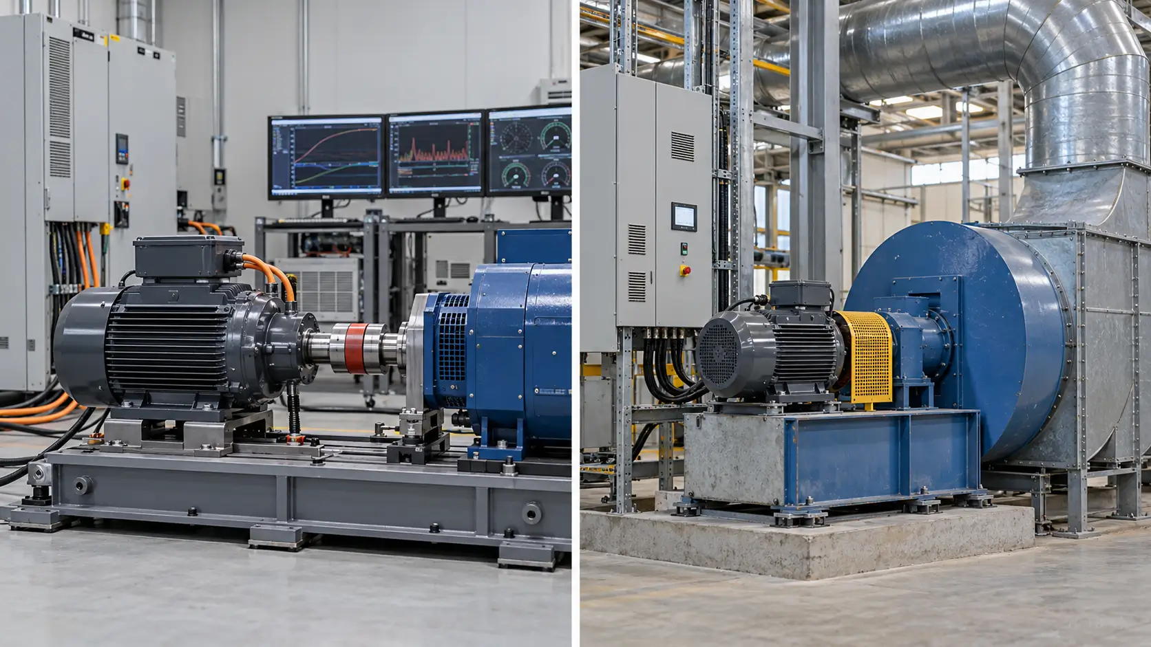
For example, reducing fan speed when full airflow is unnecessary can cut system energy use, but that saving must not be presented as a motor-efficiency improvement alone. Use comparable test conditions and the actual load profile when estimating electrical consumption or payback.
Motor Types (Surface Permanent Magnet Synchronous Motor – SPMSM vs. Interior Permanent Magnet Synchronous Motor – IPMSM)
Surface and interior magnet designs use different rotor arrangements. Neither is universally better. The relevant differences are the required torque-speed operating range, mechanical speed limits, inverter control strategy, cost and project-specific performance targets.
1.Surface Permanent Magnet Synchronous Motor (SPMSM)
In an SPMSM, the magnets are mounted at or near the rotor surface. This configuration can offer relatively straightforward rotor construction and predictable electromagnetic characteristics when appropriately designed.
SPMSMs are used in industrial fans, pumps and precision drives where the specified torque, speed range and mechanical requirements suit the design. Rotor retention and permissible maximum speed still need verification, especially at higher speeds.
2.Interior Permanent Magnet Synchronous Motor (IPMSM)
In an IPMSM, magnets are embedded inside the rotor. Rotor saliency allows reluctance torque to contribute alongside permanent magnet torque. Depending on the motor and inverter design, this can support useful torque production and a wide speed range with appropriate field-weakening control.
For a high-speed industrial drive, consider an IPMSM when its torque-speed characteristics and mechanical construction provide a clear advantage. The decision should be based on curves and verified operating limits, not the rotor designation alone.
The following qualitative comparison is a starting point for supplier discussions rather than a substitute for model-specific data.
| Selection factor | SPMSM | IPMSM |
|---|---|---|
| Magnet arrangement | Magnets at or near the rotor surface | Magnets embedded within the rotor |
| Reluctance torque contribution | Usually limited in a conventional design | Can contribute to total torque |
| Extended speed range | Depends on voltage limits and motor design | Can offer advantages with suitable field weakening |
| Selection evidence | Torque-speed curve, maximum speed, rotor retention | Torque-speed curve, control settings, rotor strength |
Back-EMF Waveform
Back electromotive force (back-EMF) is the voltage generated in the windings when the permanent magnet rotor turns. Its magnitude and waveform affect inverter compatibility, speed capability and current control.
Many PMSMs are designed for approximately sinusoidal back-EMF and sinusoidal current control. When the drive is correctly configured, this can support smooth torque production and help limit unwanted torque ripple. The real outcome also depends on machine design, current measurement and controller tuning.
For a motor-and-drive replacement, ask for the relevant back-EMF constant or waveform information when required by the inverter. Do not assume that all permanent magnet motors use the same commutation method or have interchangeable electrical parameters.
Rotor Inertia
Rotor inertia influences the torque needed to accelerate and decelerate the motor. Lower rotor inertia can be helpful for rapid indexing and frequent speed changes, but the inertia of the driven equipment and the transmission can be just as important.
Compare the combined mechanical inertia with the available peak torque and drive current, particularly for servo axes, pick-and-place machinery and cyclic conveyors. For a large inertia load, selecting a low-inertia motor without considering acceleration torque may not improve performance.
Cooling Methods
Cooling determines how much heat the motor can remove during continuous and changing loads. The correct choice depends on power losses, ambient conditions, available airflow, installation space and the required speed range.
1.Air Cooling
Natural convection and suitable air paths may be sufficient for some lower-loss or lightly loaded motors. Their continuous rating must be checked at the actual ambient temperature and installation position.
2.Liquid Cooling
A liquid-cooled motor can remove substantial heat from a compact package, which may suit high continuous loads or restricted airflow. Check coolant type, required flow, inlet temperature, pressure, connections, leakage protection and maintenance access against the specific motor documentation.
3.Fan Cooling
Forced-air cooling uses a fan to increase heat transfer. For a shaft-mounted fan, cooling effectiveness can decline as motor speed decreases. If the machine requires sustained low-speed torque, verify whether separately powered ventilation or a different cooling method is needed.
Sensor-based vs. Sensorless Control
Both methods can control a PMSM, but their performance at startup, very low speed and under rapid load changes can differ. The choice should follow the actual accuracy, wiring and maintenance requirements.
1.Sensor-based Control
Encoders, resolvers or appropriate Hall sensors provide rotor position information to the drive. This is valuable for precise positioning, repeatable startup and applications that need reliable low-speed or standstill control.
For an industrial positioning axis, confirm the sensor type, resolution, electrical interface and environmental suitability together with the controller requirements.
2.Sensorless Control
Sensorless drives estimate rotor position from electrical measurements and a motor model instead of using a separate rotor position sensor. This can simplify wiring and reduce components, making it attractive for some fans, pumps and process drives.
Conventional back-EMF estimation becomes difficult at standstill or very low speed. Advanced control methods can reduce this limitation, but the minimum controllable speed and starting torque should be verified for the proposed motor-drive combination.
Control System Compatibility
Check the motor and inverter as a matched system before purchase. A nameplate power match does not establish electrical or control compatibility. The required operating envelope must fit within both motor and drive limits.
Voltage Requirements
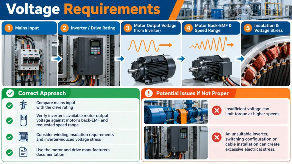
Compare mains input with the drive rating, then verify the inverter’s available motor output voltage against the motor’s back-EMF and requested speed range. Also consider winding insulation requirements and inverter-induced voltage stress.
Insufficient voltage can limit torque at higher speeds. An unsuitable inverter, switching configuration or cable installation can create excessive electrical stress. Use the motor and drive manufacturers’ documentation rather than relying on a simple voltage-number match.
Current Capacity
The inverter must support the current needed for continuous operation and the higher current that may be required during starting, acceleration or short overloads. Motor and drive ratings must both be checked, including permissible duration and thermal conditions.
For a fully loaded conveyor, the limiting condition may be startup rather than steady operation. Review peak torque demand, overload duration and protection settings. A drive that cannot deliver the required current may limit acceleration or trip even when its nominal power appears suitable.
Control Algorithm
Field-Oriented Control (FOC) is widely used with PMSMs because it separately regulates current components associated with magnetic flux and torque. Properly configured FOC can support efficient torque control and responsive operation over the intended speed range.
Successful control depends on correct motor parameter settings, current feedback, rotor position estimation or sensing, and commissioning. Verify that the selected drive supports the specific PMSM and its required operating mode. Do not assume that any standard induction-motor inverter can automatically run a PMSM correctly.
Feedback Devices
Where closed-loop control is required, verify encoder or resolver compatibility with the drive. Important details include supply voltage, signal format, resolution, wiring, shielding and any communication protocol supported by the feedback device.
Incorrect feedback configuration can cause poor speed regulation, startup faults or unstable position control. For CNC machinery, assess feedback together with mechanics, calibration and the complete motion-control system; motor choice alone cannot guarantee machining accuracy.
Communication Interfaces
Industrial drives may connect to a programmable logic controller (PLC) or other machine controller through EtherCAT, CAN-based networks, Modbus or other supported interfaces. These protocols carry commands, status information and fault data between control devices rather than directly between the PLC and motor windings.
Select the interface according to synchronization requirements, update rates, existing network architecture and available drive functions. Also confirm protection inputs, emergency stop integration and commissioning access where relevant.
Before approving a motor-drive pairing, compare the following items with the actual application requirements.
- Motor rated voltage, rated speed, continuous torque and allowable peak torque
- Drive input supply, supported PMSM control mode and output current limits
- Required operating speed range, starting torque and acceleration profile
- Motor parameter data, feedback interface and commissioning requirements
- Cooling, temperature limits, overload protection and installation conditions
- PLC communication protocol and machine safety integration requirements
Application Examples
Actual load behavior is more useful than a broad industry label. The following industrial scenarios show which operating variables usually deserve the greatest attention during PMSM selection.
Industrial Pumps and Compressors
For a centrifugal pump, start with the duty point, required flow, head and operating range. The motor must provide the torque needed across the intended pump curve, while the drive and process controls determine how the system responds to changing demand.
For a compressor, check the specific compressor technology, pressure range, start conditions and load profile. A suitable motor for a centrifugal pump is not automatically suitable for a positive-displacement compressor, even at the same rated power.
Robotics
Industrial robotic axes prioritize dynamic torque, repeatable motion and compatibility with servo controls. Motor selection should reflect acceleration time, axis inertia, gearing, operating cycles and the required feedback precision.
A compact PMSM servo can support rapid motion when the complete system is properly matched. However, robot positioning accuracy also depends on mechanical stiffness, sensors and control calibration, not simply on motor rotor inertia.
CNC Machines/Machine Tools
CNC spindles and feed axes have different demands. A spindle may require a broad speed range and suitable thermal performance at continuous load, while a feed axis often prioritizes torque response, repeatable positioning and stable low-speed control.
Assess the motor, inverter or servo drive, encoder, transmission, machine rigidity and cooling as one system. A motor specification by itself cannot establish machining tolerances or surface finish.
HVAC Systems (Fans, Pumps)
In industrial ventilation and HVAC installations, PMSMs can be considered for variable-speed fans and circulation pumps when their operating envelope and controls suit the equipment. Begin with the actual airflow, static pressure or pump head requirements, rather than a claimed motor energy-saving percentage.
Where demand varies, a properly designed speed-control strategy can reduce energy consumption. Evaluate the full fan or pump system, its load profile and the motor-drive efficiency at relevant operating points before estimating savings.
Conveyors and Material Handling
Conveyors may impose high starting torque, large inertia and frequent stops. Record the fully loaded starting condition, line speed, acceleration time, operating hours and whether the load can reverse or jam.
For a retrofit, also confirm gearbox ratio, shaft dimensions, mounting interfaces, braking and overload protection. A PMSM is a viable choice only when the proposed motor-drive arrangement meets both the electrical and mechanical requirements of the conveyor.
Final Motor Selection Checklist and Technical Review
A practical motor recommendation requires more than a requested power rating. The next step is to compare your machine’s operating data against a candidate motor’s torque-speed curve, thermal rating, inverter requirements and mechanical dimensions.
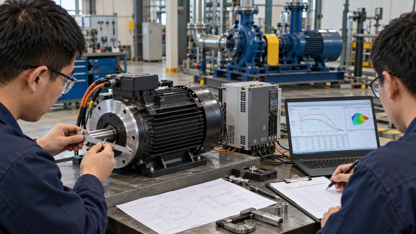
For a technical discussion or a supplier quotation, prepare the information below. It allows the engineering team to check feasibility and identify missing specifications before selecting a standard or customized PMSM.
- Equipment type and an explanation of the driven load
- Required shaft power, continuous torque, peak torque and speed range
- Starting, acceleration, braking and overload requirements
- Duty cycle, daily operating hours and expected load variations
- Available power supply and existing inverter or PLC model
- Ambient conditions, cooling arrangements and any special safety requirements
- Mounting dimensions, shaft interface and available installation space
- Existing motor nameplate, drawings or performance curves for replacement projects
If only some data is available, begin with the equipment duty, load behavior and existing nameplate information. Hiest can use those details as the basis for a technical discussion, while final suitability should be confirmed against the specific product data and required engineering checks.