

Rotor magnet retention and rotor balancing are one coupled decision rather than two separate finishing steps, because the retention structure determines where mass sits and which corrections remain possible afterwards. The usable order is operating conditions first, then retention method, then balancing position and acceptance basis, and only then cost structure, and changing anything early in that chain invalidates the decisions made later. Differences between two quotations usually come from tooling amortization, the number of balancing operations, inspection scope and scrap ownership, not from the magnet price. Every value that would make these statements specific, including tolerances, balance grades, permissible residual unbalance and process capability, has to be confirmed against drawings and inspection records before tooling is released.
This article is written from the position of a rotor manufacturer, and it deliberately separates two things that are easy to blur. Rotor process principles hold generally, while a specific factory’s process capability does not exist until it is confirmed against drawings and inspection records.
Most PMSM content starts with the motor and works backwards to the rotor. This article does the opposite. It treats the rotor as a manufacturing object with two coupled production tasks, which are holding the magnets in place and balancing the assembly, and it asks what those tasks cost when they are planned together and what they cost when they are not.
The rotor is one station inside a longer manufacturing flow. An overview of how a permanent magnet motor is built covers stamping, winding and assembly, and what follows stays downstream of that sequence, at the level of the individual rotor.
Scope of Rotor-Level Manufacturing Decisions, Not Motor Selection
A PMSM rotor has to satisfy two requirements at the same time, and neither is a finishing step. Magnets must stay in position under every condition the rotor will meet, including overspeed and thermal cycling. The assembly must also run with residual unbalance low enough for the bearing system and the noise target.
These two requirements are not sequential. The retention structure determines where mass sits on the rotor, and therefore what the initial unbalance looks like. The balance requirement feeds back into the retention structure, because it constrains where material may be removed, how thick a sleeve may be, and how much adhesive thickness variation can be tolerated. Changing one changes the other.
Because of that coupling, the useful decision sequence runs from operating conditions to retention method, then to balancing position and acceptance, and only then to cost. Reversing the order, which means selecting a retention method first and treating balance as a correction at the end, is what produces rework, late process changes, and quotations that cannot be compared.
Statements about mechanics, sequence logic and cost structure hold as general process principles. Statements about what a particular supplier can achieve do not appear here, because no drawing, process sheet or inspection record was available.
Why Magnet Retention and Rotor Balance Cannot Be Engineered Separately?
If the operating speed changes, if the retention method changes, or if the assembly sequence changes, the balance result changes with it. That single sentence is the reason the two tasks cannot be handed to different teams on different schedules. A rotor that balances acceptably in one configuration does not carry that result into another, and a balance correction performed before the retention process is finalized is a measurement of an intermediate state, not of the part that ships.
The coupling has a structure a project team can walk through, and each layer has its own open questions.
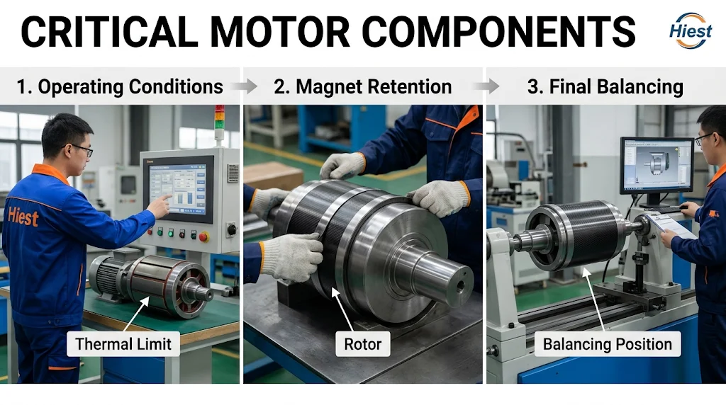
- The first layer is input conditions, which covers maximum continuous speed and overspeed requirement, the load spectrum, magnet material and its temperature limit, and the rotor’s radial and axial envelope. These are customer-side inputs and they are frequently incomplete at the first technical discussion.
- The second layer is structural constraint, which covers which retention method is feasible given those inputs, and what that method does to mass distribution and to the areas of the rotor that remain machinable.
- The third layer is process constraint, which covers where balancing can physically be performed, at what point in the sequence, and what correction methods remain available at that point.
A project that has answers at the first layer but not the second and third is not ready to release tooling. The three-layer split is an analytical framework, not a description of any particular factory’s routing.
Where Unbalance Originates in a PMSM Rotor?
Initial unbalance in a PMSM rotor usually comes from four sources.
- Magnet-to-magnet variation in mass and magnetic properties.
- Deviation in slot position, or in the placement of surface-mounted magnets.
- Uneven mass in the retention hardware, which includes sleeve wall thickness, banding tension and adhesive layer, and wedge fit.
- Eccentricity between shaft and core, introduced by fit and press assembly.
What matters more than the list is when each source becomes measurable. Magnet mass variation and core geometry can be measured at the component stage. Adhesive layer unevenness, sleeve wall thickness variation and banding overlap appear only after assembly, and some of them appear only after the retention process has cured or the sleeve has been fitted. A source that cannot be measured until after the retention step cannot be corrected before it, which means the correction window for that source is downstream by construction.
Which source dominates is a property of the specific design, not a general rule. The way to establish it is to compare component-stage measurements against assembled-rotor measurements and see which difference accounts for the observed vector. Assuming a dominant source from experience, without that comparison, usually leads to correction effort applied at the wrong stage.
The consequence for correction is direct. If the dominant contribution comes from retention hardware, then material removal and weight addition have to be planned around the magnet area rather than through it, and the choice of correction plane narrows. If the dominant contribution comes from magnet position, the correction may belong in the assembly process itself, because no amount of material removal at the balance station will fix a geometric placement error. Distinguishing these two cases before the balance operation is what separates a correction from a rework loop.
A source counts as identified only when it can be measured at a defined stage. A source that appears at neither the component stage nor the assembled stage cannot be corrected at all, and a project that has not made this distinction is not yet in a position to choose a balancing strategy.
How the Retention Method Limits Correction Options?
Balancing is, mechanically, the addition or removal of mass. Every correction method therefore needs a location on the rotor where mass can be changed without compromising the structure that holds the magnets. That is the whole constraint. Correction freedom is a function of the retention structure, not an independent parameter that can be optimized afterwards.
For surface-mounted bonded magnets, correction is normally available on the core outside the magnet footprint, or on balance planes at the rotor ends. What is not available is reworking the adhesive layer itself. Cutting into a cured bond to adjust mass risks the joint that is holding the magnet, and the magnet that would be disturbed is usually the expensive component.
For embedded magnets with wedges or potting, the slot openings and end cavities that would otherwise serve as correction space are occupied by wedge and potting material. Correction planes shift outward, toward the end faces or the outer diameter, and the amount of material that can be removed is limited by the geometry that remains. The retention structure has, in effect, spent the correction budget in advance.
For sleeve and banding retention, the magnet region is closed once the sleeve is fitted or the banding is cured. Correction is then confined to the sleeve’s outer surface or the rotor ends, and any change to sleeve wall thickness simultaneously alters the air gap and the hoop preload that holds the magnets. A parameter that appears to be a balance variable is in fact an electromagnetic and structural variable as well.
This is why adhesive thickness, potting fill, sleeve wall thickness and wedge fit must be fixed at the design stage rather than adjusted at the balance station. Each of them carries two objectives at once, which are retention integrity and mass distribution, and a change made late to satisfy one will move the other.
A correction method is usable only if mass can be changed without cutting into the retention zone. If the only reachable location sits inside that zone, the method is not available, and the project is not deciding between correction options. It is deciding whether the retention method itself is acceptable.
Magnet Retention Methods and What Each One Constrains Downstream
Four retention paths are in common industrial use, and each one imposes a different set of downstream constraints.
- Surface bonding.
- Embedded magnets retained by wedges or potting.
- A non-magnetic retaining sleeve.
- Banding with a non-magnetic tape.
The difference between them is not a ranking of holding strength. It is the combination of added mass distribution, rework feasibility, reachable correction area and inspection method that each one imposes.
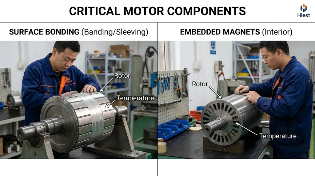
This section evaluates them on those four criteria rather than on strength, because strength is usually the criterion already covered in the design calculation, while the downstream process consequences surface later, at the balance station, at first article inspection, or in a scrap report.
What the reader should carry out of this section is a shortlist of feasible paths for their own combination of speed, overspeed requirement, magnet material and temperature, and air gap budget, plus, for each path, the constraints it imposes.
Surface-Mounted Bonded Magnets, Process Dependencies and Rework Limits
Surface bonding depends on three upstream processes that are easy to treat as routine and expensive to get wrong. Rotor surface preparation determines what the adhesive can actually bond to. Adhesive layer thickness control determines magnet position and the local mass distribution that the balance operation will later have to correct. Cure conditions determine whether the bond reaches its intended strength at all.
Variation in any of the three shows up as variation in the assembled rotor, and often as variation that is not visible. A magnet that sits a fraction of a layer too high is a mass eccentricity. A bond that has not fully cured is a joint that will fail under thermal cycling or overspeed rather than during assembly.
The process consequence is that inspection has to precede balancing. Appearance checks and bond strength sampling after cure should be complete before the rotor reaches the balance station, because a rotor that is balanced and then rejected for bond quality has consumed balance capacity for nothing. It also means the balance sequence has to be planned around the cure, not around the assembly of the magnets.
Rework on a bonded rotor is largely destructive. Removing a magnet generally destroys the magnet, disturbs the surface preparation beneath it, and leaves the surrounding bond to be re-established. A bonding defect therefore tends to convert into a scrapped rotor rather than a repaired one. On routes where rework is irreversible, this is the mechanism through which bonding defects reach the scrap line at all. How large that share actually is depends on the route and cannot be stated without the factory’s own records.
The process is judged acceptable when surface preparation, adhesive thickness and cure each have records, and when inspection is complete before the rotor reaches the balance station. If any of those three is missing, the balance result describes an assembly whose retention quality is still unknown.
Embedded Magnets with Wedges or Potting, Access and Inspection Constraints
Embedding magnets in slots changes the space available for correction. Wedges and potting fill the slot openings and the end cavities that would otherwise be convenient removal sites, so the correction planes move outward and the removable material is limited by the surrounding lamination geometry. The rotor can still be balanced, but the leverage available at the balance station is smaller than the geometric envelope suggests.
Potting also changes what can be inspected. Once the magnet is encapsulated, the slot interior cannot be examined visually on a piece-by-piece basis. Inspection shifts to process parameter records, sampled destructive cross-sections, and indirect electrical or magnetic checks. That is a legitimate inspection strategy, but it changes when a defect becomes visible. Problems that would appear at a visual check in an open structure instead appear at balancing, at overspeed test, or later.
The sequence constraint follows from the cure. Potting has to be cured before the rotor is balanced, because the potting is part of the mass distribution being measured. That fixes the order of insertion, potting, cure and balance, and removes the option of balancing an open rotor and correcting afterwards. Projects that plan for a correction loop after potting are planning for a loop that does not exist.
Potting is judged acceptable when cure records exist, sampled cross-sections confirm fill in the intended locations, and balancing is sequenced after cure rather than before. Where any of the three is absent, the inspection method has not been defined, only the intention to inspect.
Sleeve and Banding Retention, Added Mass, Air Gap, and Balance Interaction
A retaining sleeve or a banding layer adds a concentric mass at the outside of the rotor. The layer itself is usually intended to be uniform, and its effect on balance is not that it creates unbalance but that it moves mass outward. Moving mass outward increases the moment of inertia and increases the contribution of any residual eccentricity to the unbalance vector, so the correction authority required changes even when the eccentricity does not.
The practical consequence is that balancing must be performed on the rotor in its final retained state. A rotor balanced before the sleeve is fitted is a different object from the one that ships, and the difference is not a scale factor that can be applied afterwards.
The sleeve is also the clearest example of a parameter that belongs to more than one discipline. It occupies radial space and therefore reduces the effective air gap. It sits in the heat path between the magnets and the environment and therefore changes the thermal behaviour of the magnet system. It carries hoop preload and therefore determines whether the magnets stay in place at overspeed. Sleeve thickness, material and fit are consequently a joint decision between the electromagnetic design, the thermal design and the manufacturing process, and a manufacturing organisation cannot set them unilaterally, nor can a customer set them without the manufacturer’s process input.
Sleeve parameters are judged settled only when the electromagnetic, thermal and manufacturing functions have each signed off on them. A value agreed by one function alone is not a decision, and a sleeve specification that has not been signed off cannot be quoted, tooled, or used as a basis for the balancing arrangement.
Where Rotor Balancing Sits in the Manufacturing Sequence?
The position of balancing in the process is not a fixed convention. It follows from one question, which is whether the mass distribution is still allowed to change after the retention operation.
If the answer is no, because the sleeve is fitted, the banding is cured, the potting is set or the adhesive has fully cured, then balancing must come after that operation and must be treated as a final inspection item. If the answer is yes, because the structure still permits material to be removed or added before the retention step is completed, then a split arrangement becomes possible, with an initial balance to establish a workable baseline followed by a final balance after retention.
Neither arrangement is better in general. A final-only arrangement has fewer operations and fewer setups, but it puts the entire correction burden after an irreversible step. A split arrangement reduces the risk of a late rejection, at the cost of additional balancing operations, additional setups and additional handling. The choice depends on the tolerance chain and on how much rework the retention method allows.
Acceptance Criteria and Documentation for a Balanced Rotor
An acceptance basis for a balanced rotor needs to fix four elements, and a document that omits any of them cannot support reproducible judgement.
- Measurement conditions, which means which balancing machine, at what capacity, measured in what way, and under what mounting condition.
- Tooling and clamping arrangement, which means how the rotor is located and with what repeatability.
- Judgement method, which means which criterion is applied, at which station the pass or fail decision is taken, and what triggers a re-check.
- Record format, which means whether records are kept per piece or per batch, and how they are retained for traceability.
Clamping and location deserve more weight than they usually receive. The same rotor measured in two different fixtures can produce two different readings, and neither is wrong, because they are measurements of different mechanical states. That is why the clamping method and the locating datum belong in the acceptance document rather than in a work instruction. Without them, batch-to-batch comparison is not a comparison of rotors, it is a comparison of setups.
Re-check triggers should also be written down rather than left to judgement. A balance performed, followed by a retention process, followed by no further check, is a common gap, because the part that was balanced is not the part that ships. The same applies after a fixture change or a change of balancing machine. Where the record granularity is too coarse to show which rotor was measured under which setup, a customer acceptance question cannot be answered from the records, and the discussion turns into a dispute about method rather than about parts.
An acceptance document is adequate when a person who was not present could reproduce the pass or fail decision from it. If the clamping method or the re-check trigger is missing, it is not adequate, regardless of how precisely the unbalance limit itself is stated.
How Retention and Balancing Decisions Drive Rotor Cost Structure?
Rotor cost is easier to discuss when it is broken into categories that respond to different decisions. Five are useful.
- Magnet and retention material.
- Dedicated tooling and one-time development.
- Process time, including the number of balancing operations.
- Inspection and testing.
- Scrap and rework.
The first of these, magnet and retention material, is where upstream price movement enters rotor cost. Rare earth metals such as neodymium and dysprosium sit at that layer, and their movement is outside anything the rotor process itself can control.
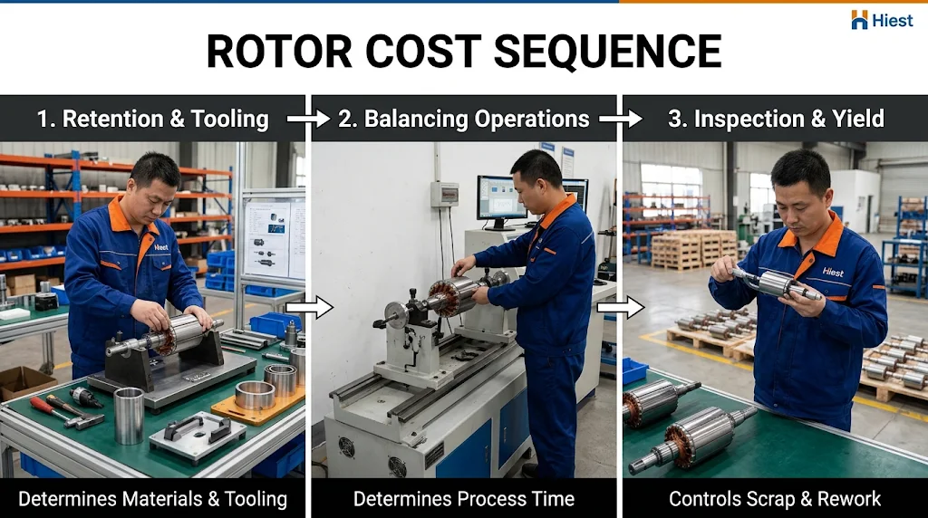
The mapping between decisions and categories is direct. The retention method changes the material list and the tooling list. The process sequence changes the number of balancing operations and therefore the labour content. The first-pass yield at balancing changes the scrap and rework line. None of these categories is visible in a quotation that lists only material and machining, which is why two quotations for what appear to be the same rotor can differ substantially and still both be internally consistent.
Comparability has a precondition. Two quotations are comparable only when four things are aligned.
- Whether tooling is listed separately or amortized.
- How many balancing operations are included.
- Whether inspection is sampled or full.
- Who carries the cost of scrap and rework.
Where any of the four differs, the unit prices are not describing the same scope, and comparing them produces a decision that the underlying data does not support.
One-Time Tooling and Development Cost versus Recurring Unit Cost
One-time cost includes the tooling tied to the chosen retention structure, the fixtures required for balancing, the machining programs and the first-article verification. These items do not scale with order quantity. They are incurred once and then either invoiced separately or spread across the order.
Spreading them changes the unit price without changing the process. The same rotor built on the same route will show a different unit cost at a different quantity, purely because the fixed component is divided differently. This is a mechanism, not a recommendation about order size, and it explains why a supplier’s unit price for a small quantity and a large quantity can differ by more than the material difference alone.
Before comparing quotations, three questions settle most of the ambiguity. Is tooling listed as a separate line or included in the unit price. If it is amortized, over what quantity. Is first-article verification charged as a separate item.
Amortization is judged settled when the quotation shows whether tooling is a separate line and over what quantity it is spread. Until those two facts are on the page, the unit prices are not comparable, whatever their numerical relationship.
The same mechanism explains why volume changes a quotation beyond the material difference. On the purchasing side this is often described as the point where per-unit cost goes down, and the underlying reason is the fixed component being spread rather than the rotor becoming cheaper to produce.
Scrap, Rework, and Inspection, the Cost Items Buyers Usually Miss
Scrap and rework arise at predictable points. Bonding that cures unevenly, retention hardware that assembles off position, and balancing that removes too much material all convert a rotor into either a rework case or a loss. The pattern differs by retention method, because a bonded or potted rotor has few reversible failure modes while a rotor with mechanically removable retention has more opportunities to correct without scrapping.
Inspection scope changes the economics of these failures as well as their detection. Sampled inspection costs less per piece but accepts a population in which some non-conforming rotors ship. Full inspection costs more per piece and exposes more of the losses internally. Neither is universally correct. What matters is that the choice is stated, because a quotation that assumes sampling and a quotation that assumes full inspection are quoting different products.
This is the category most often absent from a comparison. When a supplier’s quotation lists material and machining only, the yield assumption and the inspection basis are hidden inside the unit price, and the buyer has no way to tell whether two prices rest on the same assumptions.
Inspection scope is judged settled when the quotation states sampled or full inspection and who carries the scrap. Absent that statement, the two prices under consideration describe different products, and the comparison has no technical basis.
What to Confirm With the Rotor Manufacturer Before Tooling or Sample Release?
Tooling freezes a process, and once it is frozen a change to the retention method or to the balancing requirement is no longer an edit to a document. It is new tooling, a new sample round and a re-sequenced balancing operation. That is why confirmation has to happen before tooling release rather than after the first sample is measured.
The confirmation divides into three groups. The customer side provides the input conditions that only the application can define. The manufacturer side confirms the process and inspection capability that only the factory can define. The two sides then agree the acceptance basis and the treatment of non-conforming parts, which neither can set alone.
Customer-side inputs
- Maximum continuous speed and overspeed requirement, including the overspeed test value.
- Operating temperature range at the magnet.
- Magnet material and the intended arrangement.
- Permitted added mass and air gap budget.
- The balance acceptance requirement, expressed in the form the customer’s own acceptance process uses.
Manufacturer-side confirmations
- Which retention processes are actually available for this rotor, as distinct from which are described in marketing material.
- Where balancing is performed in the route, and how many balancing operations the route assumes.
- Balancing machine capacity and fixture repeatability.
- Which inspection items are performed, at which stage, and against which criterion.
Joint agreements
- The acceptance basis, in the four-element form described earlier.
- The re-check triggers after retention.
- The disposition of non-conforming parts, whether rework, downgrade or scrap, and who carries each outcome.
The consequence of leaving any of these open is specific rather than general. An unconfirmed speed or overspeed requirement can invalidate the retention choice and therefore the tooling. An unconfirmed balance acceptance basis can leave the inspection station unable to pass or fail a part consistently. An unconfirmed scrap disposition turns a quality discussion into a commercial one after the fact. None of these are hypothetical risks. They are the ordinary failure modes of a rotor project that moved to tooling before the confirmation was complete.
Conclusion
The practical output of this article is a confirmation set rather than a recommendation. Before tooling or sample release, four things should be fixed in writing.
- The final form of the magnet arrangement and retention method.
- The position of balancing in the route and the acceptance basis that will be applied.
- The inspection items and the criterion behind each one.
- The agreed treatment of non-conforming parts.
Each has a cost consequence that is easy to overlook at the time. An unsettled retention method means tooling that may have to be remade. An unsettled balancing position means an extra operation, or a re-sequenced route, discovered after the first samples. An unsettled acceptance basis means a re-check that cannot be judged against anything. An unsettled disposition means scrap and rework with no agreed owner.
One boundary belongs with the checklist. Specific delivery dates, sample rounds and verification cycles cannot be promised at this stage, because they follow from the confirmed process rather than from the intent to proceed.
The next step is the confirmation meeting itself. Take the three lists from the previous section into it, covering customer inputs, manufacturer confirmations and joint agreements, and do not release tooling until each line has an owner and a documented answer. Once the rotor requirements are confirmed, the same discipline transfers one level up, to how those requirements are verified at motor level. That verification logic is described in how to choose a permanent magnet synchronous motor, and the inspection items above belong inside the supply chain controls outlined there.