
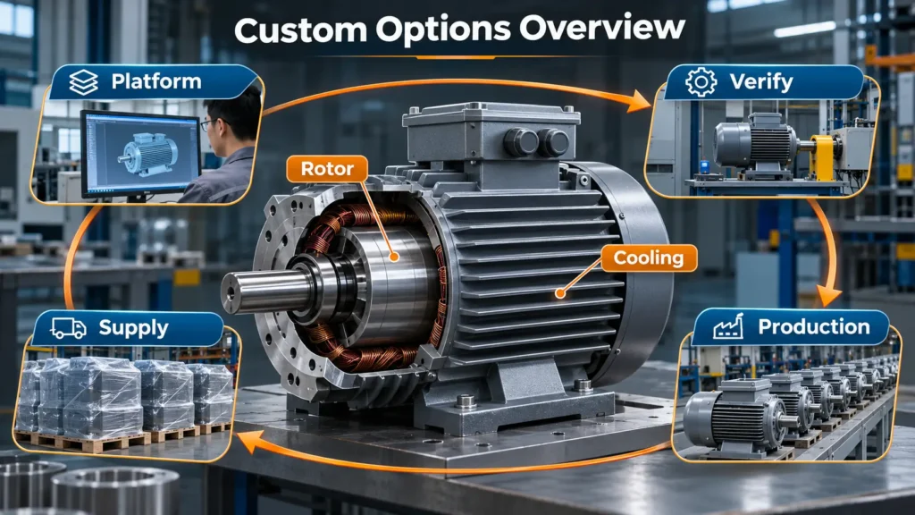
When assessing manufacturing partners, it helps to understand how a custom permanent magnet synchronous motor (PMSM) moves from an application requirement to a released manufacturing definition through a series of controlled engineering decisions. The final drawing is an important output, but it is not the first document created or the only document needed to build the motor. An initial specification becomes a design brief, the design brief informs electromagnetic, thermal, and mechanical work, and controlled prototype drawings and a provisional bill of materials (BOM) allow a sample to be built and evaluated. Test findings and interface reviews may send the project back for changes before the approved manufacturing package is released.
The practical question at every stage is what has been confirmed and what remains an assumption. A motor can meet a nominal power rating yet fail to fit the customer’s shaft interface, remain within its temperature limits, or operate with the intended inverter over the full torque speed range. These gaps must be resolved in the relevant design documents rather than hidden in a drawing revision. A released drawing establishes an engineering baseline, and permission to start repeatable production also depends on material, process, inspection, and any agreed first article or pilot production requirements.
This article follows the document chain from specification to engineering review, prototype drawings, sample validation, released drawings, and subsequent change control. It explains what each handover must establish and what a manufacturer needs from the customer. The sequence is a general engineering framework, not a representation of an unverified Hiest internal approval procedure.
Which Documents Move a PMSM from Specification to Released Drawings?
The document chain makes engineering decisions traceable. It does not need to be strictly linear, since simulations, mechanical layouts, prototype drawings, sample preparation, and test planning can overlap when the configuration and assumptions are controlled. The important distinction is between a working definition, an approved prototype configuration, and the manufacturing definition released for repeatable production.
| Document or state | What it establishes | Decision before the next stage |
|---|---|---|
| Application specification and design brief | Required torque speed duty, supply and drive conditions, interfaces, environment, and open assumptions | Are the critical application constraints sufficiently understood for preliminary design |
| Engineering design record | Electromagnetic, thermal, structural, and control interface analyses, selected configurations and design rationale | Which concepts can proceed to a controlled prototype |
| Prototype drawings and provisional BOM | Buildable sample geometry, materials, winding instructions, interfaces, and identified departures from final requirements | Is the prototype defined well enough to build and test against agreed objectives |
| Prototype and verification records | Measured performance, observed problems, test conditions, deviations, and corrective actions | What must change, and which requirements have been verified |
| Released manufacturing package | Approved part and assembly drawings, BOM, materials, winding and process instructions, inspection criteria, and revision references | Is the product definition complete for manufacturing preparation |
| Production readiness approval | Applicable tooling and fixture readiness, material control, process capability, first article or pilot evidence, and quality arrangements | Can the agreed configuration be produced and inspected repeatably |
A change to a motor’s torque speed requirement may reopen electromagnetic and thermal calculations. A change to a mounting interface may affect machining drawings, bearing arrangements, or housing geometry. A substitute material may need a revised BOM and additional validation without changing the geometry at all. The document affected depends on the technical impact, not simply on when the change arrives.
What Must a PMSM Specification Establish Before Detailed Design?
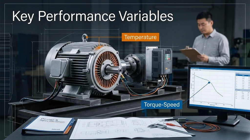
A useful specification defines an operating envelope rather than a single rated point. The key inputs are load and duty, electrical supply and inverter limits, installation interfaces, environmental constraints, and the acceptance requirements that will later be tested. If information is incomplete, engineering can begin with documented assumptions or design scenarios, but those assumptions cannot silently become approved specifications.
Continuous and short duration torque must be evaluated against combined motor thermal limits, inverter current and voltage limits, electromagnetic characteristics, mechanical constraints, and the application duty cycle. Base speed and field weakening performance depend on the motor’s back EMF, inductances, inverter voltage and current limits, and control strategy. DC bus voltage matters, but it does not independently determine the achievable speed range. When the motor family has not yet been chosen, matching PMSM torque and speed characteristics to the application is a useful step before the detailed design brief is fixed.
Drive information is part of this engineering basis. The available output voltage and current, overload capability, supported PMSM control mode, motor parameter requirements, feedback interface, and switching conditions can affect winding, insulation, losses, and commissioning. The actual drive model and operating requirements should be evaluated together when confirming PMSM compatibility with an existing VFD. A compatible connector or nominal voltage is not enough to establish a compatible motor drive system.
Not every detail must be fixed on the first day. Branding, packaging, or marking content may be finalised later if the deferred decision has no effect on thermal performance, mounting, environmental protection, regulatory information, or product identification. Surface coatings and treatments require particular care because they can affect fit, corrosion resistance, insulation, heat transfer, or assembly. The engineering team should record what is provisional, the assumptions used, and the latest stage at which the item must be resolved.
When an Existing Motor Is Used as the Reference?
An existing motor or physical sample can shorten the discovery stage, but it is a reference rather than a complete application specification. Its nameplate may not describe transient load, the original inverter setup, the full duty cycle, or the installation environment. A replacement or custom derivative should therefore be assessed against the actual machine requirements rather than developed solely from the reference model number.
The review may use available torque speed data, rated and peak operating points, duty information, winding resistance and inductance, back EMF at a stated speed, drive and feedback details, cooling conditions, and existing test records. Where measurements are needed, their feasibility depends on the condition of the reference motor and the available test setup. An unmeasured quantity should be marked as unknown or assumed, not converted into a verified design input.
The physical interface needs its own check. Shaft diameter and extension, keyway or spline, flange pilot, mounting hole pattern, bearing interfaces, overall envelope, cable outlet, and feedback connections can differ from an archived drawing or a worn sample. The measured or otherwise confirmed interface should become a controlled requirement with a clear revision reference.
Which Electrical, Mechanical, and Environmental Interfaces Cannot Be Left Ambiguous?
Before the corresponding detailed design or drawing is approved, the responsible parties need clear dimensions and performance limits for the shaft and mounting arrangement, space envelope, cable and connector interface, supply, drive, feedback, and environmental conditions. Missing information does not always stop concept work, but it blocks approval of the affected manufacturing definition when the designer cannot establish a safe and verifiable assumption.
The engineering impact also varies. Changing a flange hole pattern may require a mounting drawing and machining review, while changing the cooling interface may affect housing geometry and the thermal model, and changing the feedback device may affect the end cap, wiring, test setup, and inverter commissioning. Each interface should have an owner, a documented source, and a required confirmation point. That prevents an approximate drawing dimension from becoming an unapproved manufacturing commitment.
How Does the Design Brief Become an Electromagnetic and Mechanical Design?
The design brief is translated into related electromagnetic, thermal, mechanical, and control interface decisions. Preliminary sizing identifies possible stator and rotor dimensions, winding and magnet configurations, operating losses, temperature limits, shaft and bearing loads, and packaging constraints. Analytical calculations and simulations help compare configurations before the team commits to prototype hardware. Controlled prototype documentation can be prepared while the analyses mature, and it does not have to wait for a final production design record.
The work is iterative because these disciplines share constraints. Winding and magnetic design affect losses and torque production. Cooling and housing geometry affect the temperature reached at a given duty point. Rotor construction has to tolerate operating speed and thermal conditions while maintaining the required air gap. A candidate that meets one domain but fails another returns to engineering review with a documented change rather than progressing on the strength of one favourable result.
How Do Magnet, Winding, Rotor, and Cooling Decisions Interact?
Magnet selection affects flux, temperature related performance, and demagnetisation margin. Winding turns and configuration affect back EMF, resistance, current requirements, and electromagnetic harmonics. Copper, iron, magnet related, and mechanical losses contribute differently across the operating range, and their relative importance depends on the actual design, speed, loading, and drive conditions. Cooling must be evaluated against that combined loss profile and the specified ambient and duty cycle.
Changing the magnet grade does not automatically require a different winding, but it can change the magnetic operating point or performance margin enough to require recalculation and renewed verification. A cooling change can alter the allowable thermal loading without necessarily changing the electromagnetic geometry. When cooling or maximum speed is still provisional, engineers may compare explicitly defined scenarios, and final approval must identify the configuration and conditions that were actually accepted.
Winding layout and magnet retention are connected through overall motor requirements, but they are not the same engineering decision. Winding layout directly influences stator manufacture and electromagnetic behaviour. Rotor magnet retention depends more directly on rotor topology, magnet geometry, speed, centrifugal loading, temperature, and the chosen mechanical retention method. Surface mounted and interior magnet configurations also differ in saliency, structural construction, and field weakening possibilities. Their suitability should be judged for the actual torque speed and rotor stress requirements rather than treated as universal advantages.
What Changes Between the First Design Pass and the Reviewed Configuration?
An initial design pass may establish candidate stack length, stator and rotor geometry, air gap, magnet dimensions, turns, current density, and expected losses. These values are preliminary until the electromagnetic, thermal, mechanical, and drive system constraints have been evaluated together. A reviewed configuration records the assumptions, analyses, selected components, remaining risks, and decisions supporting the next prototype or design revision.
Changes should be routed according to their technical effect. A new torque requirement, speed limit, cooling condition, or magnet choice may require renewed sizing and verification. An annotation or non critical marking change may affect only a drawing or marking specification. A small geometric change can still affect the magnetic path, bearing fits, or process capability. The correct test is whether the change affects an approved requirement or validated characteristic, not whether it appears minor on the drawing.
How Is a Reviewed PMSM Design Converted Into a Buildable Manufacturing Package?
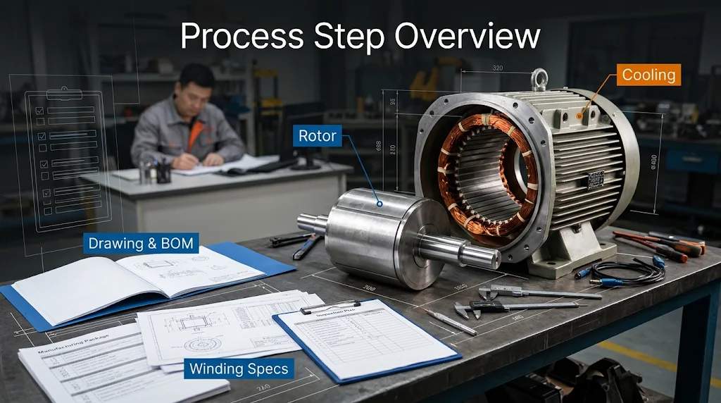
A manufacturing drawing is an executable part of the design definition, but a complete motor normally requires more than one drawing. Part and assembly drawings define geometry and interfaces. The BOM identifies approved materials and components. Winding specifications define turns, connection scheme, and related manufacturing details. Process or work instructions may define rotor retention, assembly and impregnation controls. Inspection plans identify measurable acceptance characteristics. The design record and test evidence explain why the released configuration was accepted.
Mechanical drawing details typically include the motor envelope, shaft and mounting interface, bearing fits, critical runout or alignment requirements, cable entry, housing and cooling interfaces, and other controlled dimensions. The corresponding electrical and manufacturing files identify winding configuration, terminals, feedback arrangement, magnetic materials, and applicable assembly and inspection references. A dimension alone cannot communicate a test condition or a manufacturing method unless the drawing explicitly references the governing specification.
Tolerances are manufacturing requirements. They should be reviewed against functional needs, the capabilities of the intended process, and the available measurement method. A very tight value without process or inspection support may be difficult to reproduce, while a loose value at a critical shaft or air gap interface can compromise performance. Process and quality planning therefore need to accompany drawing review rather than follow it as an unrelated administrative task.
What Belongs in the Drawing, BOM, and Design Record?
The drawing describes geometry and interfaces the production team can manufacture and inspect. The BOM and material specifications control the approved component and material choices. Winding, assembly, and process instructions translate the design into the steps used to build the motor. The design record retains calculations, assumptions, simulation results, and rationale. Verification records connect measured outcomes to the tested configuration and test conditions.
These documents are linked through identifiers and revisions. If a shaft drawing changes, engineers must assess its impact on relevant interfaces, fixtures, and verification evidence. If a supplier changes a material within an otherwise unchanged geometry, the BOM or material specification may need revision even when the drawing does not. Documentation control should preserve the relationship between the approved requirements, the actual manufactured configuration, and the evidence supporting its release.
Who Approves the Drawing and What Does the Approval Mean?
Drawing review should check the design record, the customer’s installation and interface requirements, and the manufacturing and inspection references. It should identify open discrepancies, approval conditions, responsible parties, and the precise revision being reviewed. A review is useful only when it produces a traceable decision, and informal confirmation without a defined document version is insufficient for a controlled release.
The buyer’s approval scope is determined by the agreement. It may cover mounting interfaces, performance specifications, relevant drawings, a prototype, sample results, or a broader technical package. The manufacturer may separately control internal manufacturing release. Neither side’s responsibility can be inferred from a signature alone, and changes after approval should follow the agreed engineering change procedure.
An interface correction may be resolved through a drawing revision if it does not alter validated performance. A change to air gap, magnetic circuit, winding, cooling, or other performance relevant characteristics requires assessment of affected design assumptions and evidence. The review record should state whether reanalysis, resampling, or additional tests are necessary before the revised configuration is released.
How Are Prototype Drawings and Performance Requirements Verified?
A prototype is built from a controlled sample configuration, often using prototype drawings and a provisional BOM rather than the final manufacturing package. Validation begins with agreed objectives, test methods, acceptance criteria, and a defined sample configuration. The resulting evidence is then compared with the requirements and engineering predictions. When deviations are found, engineers assess their cause, update the relevant documents or process, and repeat affected verification as needed.
The tests selected depend on the design and project. Back EMF at a specified speed, winding resistance under recorded temperature conditions, torque speed performance, temperature rise, vibration, and other characteristics may be evaluated where suitable procedures and equipment are available. Measuring losses, torque ripple, or rotor stress can require specialised equipment, analysis, or indirect methods, and they should not be described as universally obtainable from a simple sample test. For converter fed motors, IEC 60034-2-3:2024 defines specific methods for losses and efficiency determination within its scope. The appropriate method must match the motor, inverter, operating conditions, and acceptance requirement.
Sample success also has a limit. One unit can support a conclusion about the configuration tested, but it does not demonstrate repeatability across production batches. The separate controls needed for repeat orders are addressed through process preparation, first article or pilot verification where required, inspection planning, and configuration traceability. The purpose and conditions of permanent magnet motor testing should be agreed against the actual characteristics that the project must verify.
How Should a Failed Test Be Investigated and Closed?
A failed validation result should lead to a documented root cause assessment before the team chooses a corrective path. Potential sources include the electromagnetic or thermal model, the released sample drawing, material variation, assembly error, inverter settings, sensor calibration, test equipment, or the measurement method. The size of the deviation alone does not reveal its origin.
If the design assumption is wrong, the relevant calculation, model, configuration and affected drawings may need revision. If the discrepancy comes from an incorrect drawing instruction, a controlled document correction may be sufficient. If assembly, component quality or test setup is responsible, the process, parts or method should be corrected and retested. The closure record should identify the cause, corrective action, affected units or documents, repeated checks, and acceptance decision. A passing repeat test without an understood cause may not resolve the underlying production risk.
What Does Drawing Freeze Mean, and How Are Later Changes Controlled?
A frozen or released drawing identifies an approved revision to be used within a defined manufacturing package. It prevents uncontrolled shop floor edits and gives engineering, production, and quality teams the same baseline. It does not, by itself, authorise mass production. Material availability, tooling and fixtures, process instructions, inspection capability, required first article or pilot results, and contractual approval may still need to be established before production release.
Changes after drawing release should follow a documented engineering change request and impact assessment. The assessment considers interfaces, tooling, materials, electrical and thermal performance, manufacturing steps, measurement methods, applicable verification evidence, affected stock, and units already built. The approved change may update a drawing, BOM, material specification, work instruction, inspection plan, or several documents together. The objective is to preserve the link between product configuration and evidence, not to force every change into the drawing revision.
How Does Revision Control Protect Repeat Orders?
A repeat order should reference a controlled set of drawing, BOM, material, process and inspection revisions. That baseline supports consistent sourcing and manufacturing, but consistency also depends on incoming material controls, process performance, test methods, and traceability. Reusing a drawing number alone does not guarantee that the next batch behaves like the first.
If a material or process substitution is proposed, the responsible team should review the characteristics it may affect and determine which records need revision and which tests should be repeated. A supplier change can be controlled without modifying geometry, while a change in the customer’s duty or inverter conditions may require a broader engineering reassessment. The approved revision and effective date should identify which units and orders are covered.
Where Can a Custom PMSM Design Project Lose Time?
Unresolved handovers are one important source of engineering delay, but not the only one. Component availability, prototype tooling, test bench access, validation findings, and production resources can also affect a project. The examples below show common dependencies without claiming that they account for a particular percentage of delays at Hiest or elsewhere.
| Handover | Unresolved item | Why it matters | Practical next action |
|---|---|---|---|
| Requirements to initial design | Missing load profile, inverter limits or cooling assumptions | Different assumptions lead to different electromagnetic and thermal designs | Record the assumption, request evidence, or review alternative scenarios |
| Design to prototype drawing | Unconfirmed shaft, mounting or cable interfaces | Prototype dimensions may not match the customer’s installation | Confirm the interface revision and ownership before approving relevant drawings |
| Prototype to validation | Missing test method or acceptance criteria | Results cannot be judged consistently | Agree on measurement conditions, thresholds and report format |
| Test result to design closure | Unresolved failure cause | A document change alone may not correct the problem | Complete root cause review and affected reverification |
| Released design to production | Material, tooling, process or inspection readiness remains open | Released drawings do not guarantee repeatable manufacture | Close the agreed production readiness items separately |
The controlling principle is to make unresolved items visible early, assign responsibility, and distinguish provisional engineering estimates from approved performance and delivery commitments.
What Information Starts a Custom PMSM Engineering Review?
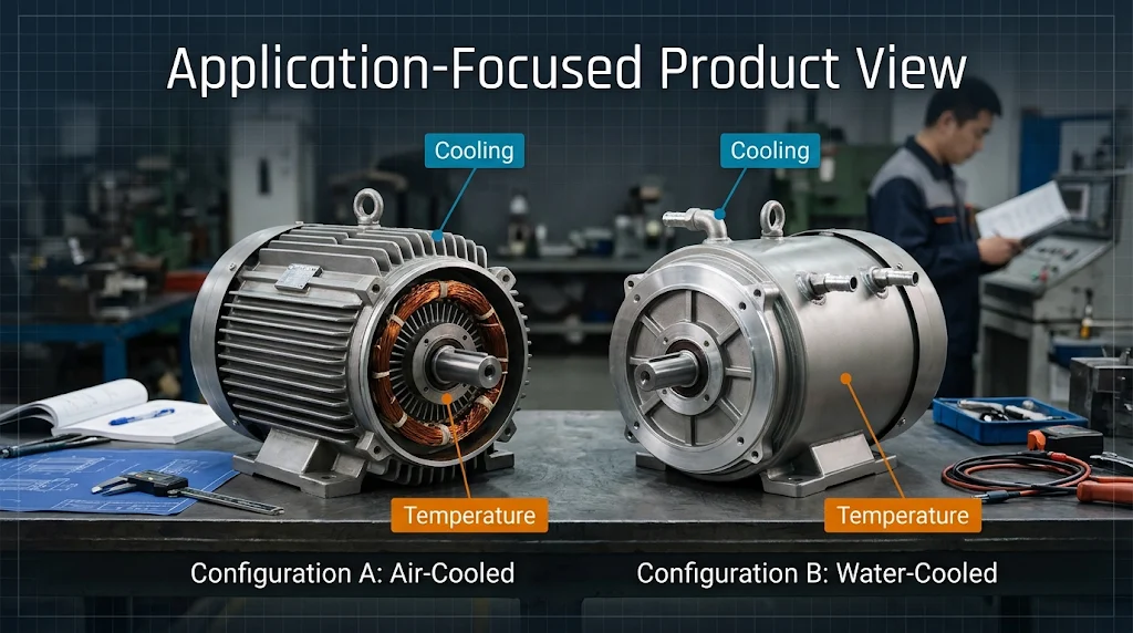
An initial review can begin before every dimension and test requirement is fixed. The manufacturer needs enough information to identify the application, evaluate plausible configurations, and record what remains unknown. Detailed design approval requires a more complete operating envelope, while prototype acceptance criteria must be established before formal verification. Production release requires the controlled manufacturing package and relevant process and quality evidence in addition to design approval.
The following table can be used as a working input checklist. The status should be filled in for the actual project using Available, Assumed, Pending, or Confirmed. The table does not imply that every item must already be confirmed before an initial enquiry.

| Input | Why it matters | Status before detailed design | Document or output |
|---|---|---|---|
| Application and load profile | Establishes starting, steady, transient and overload conditions | Available / Assumed / Pending / Confirmed | Application brief and duty assumptions |
| Continuous and peak torque | Constrains electrical, thermal and mechanical sizing | Available / Assumed / Pending / Confirmed | Torque requirement and acceptance points |
| Operating speed range | Determines base speed, maximum speed and field weakening needs | Available / Assumed / Pending / Confirmed | Torque speed operating envelope |
| Duty cycle and thermal limits | Defines allowable heating under actual use | Available / Assumed / Pending / Confirmed | Duty and temperature assumptions |
| DC bus, inverter and current limits | Constrains winding, control, losses and commissioning | Available / Assumed / Pending / Confirmed | Motor drive interface requirements |
| Mechanical envelope and shaft mounting | Determines fit, bearings and relevant drawings | Available / Assumed / Pending / Confirmed | Interface drawing or reference dimensions |
| Feedback, connectors and wiring | Affects mechanical and electrical interfaces and test setup | Available / Assumed / Pending / Confirmed | Feedback and connection specification |
| Cooling, ambient and protection | Affects thermal, sealing and housing design | Available / Assumed / Pending / Confirmed | Environmental design basis |
| Required verification and documentation | Defines what must be measured and recorded | Available / Assumed / Pending / Confirmed | Draft validation and acceptance plan |
| Expected sample and production volumes | Informs the proposed development and production route | Available / Assumed / Pending / Confirmed | Project planning assumptions |
Hiest’s permanent magnet and PMSM engineering background provides context for an initial discussion of magnetic configuration, motor performance, mechanical interfaces and application constraints. An enquiry can begin with available load, inverter, installation and environmental information. The actual deliverables, such as a preliminary configuration, engineering drawing package, sample plan, test records, quotation, or production schedule, must then be agreed for the specific project, and they should not be inferred from a generic design sequence or presented as an existing Hiest standard workflow without internal verification.
The next useful action is to send the available specification or reference motor information, identify outstanding fields, and request an initial technical review. The response should distinguish confirmed requirements from assumptions, identify the next engineering or sample decision, and explain which approvals are needed before manufacturing documentation and production conditions can be committed.
Conclusion
A custom PMSM design develops through a controlled relationship between application requirements, electromagnetic and mechanical analysis, prototype drawings, test evidence, and released manufacturing documents. The steps can iterate, but the approved configuration and its rationale must remain traceable. A drawing is meaningful when it is linked to the BOM, materials, winding and process instructions, acceptance criteria, and evidence supporting the design, and not merely when dimensions have been added to a page.
For a project to move forward, define the available torque speed and duty requirements, motor drive interface, shaft and mounting constraints, cooling and environmental conditions, and intended verification scope. Mark missing information as assumed or pending, rather than allowing it to become an unstated requirement. Prototype findings should be resolved through documented root cause and change control, and a released drawing should be distinguished from a separate decision that the process is ready for repeatable production. These controls turn a preliminary specification into a manufacturing definition that can be reviewed, tested, changed, and reproduced with accountability.