
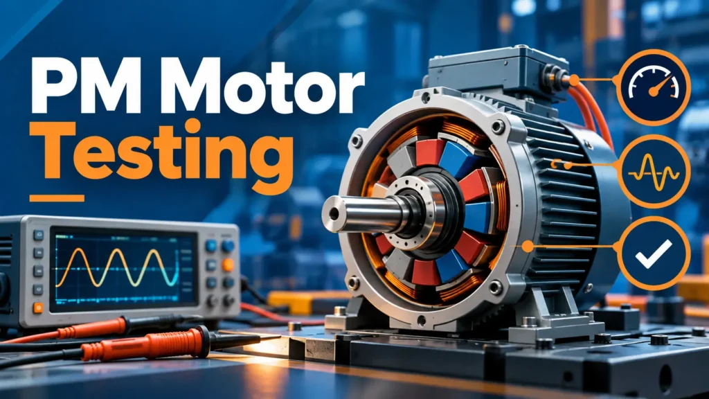
Permanent magnet motor testing evaluates the electrical condition, magnetic performance, mechanical integrity, and operating characteristics of a motor. Common methods include insulation resistance testing, polarization index measurement, winding resistance testing, surge testing, rotor inspection, vibration analysis, and back electromotive force measurement.
The appropriate tests depend on the motor design, rated specifications, operating conditions, and purpose of the inspection. For example, insulation resistance testing helps identify weaknesses in winding insulation, while vibration analysis can reveal possible mechanical problems. Back-EMF testing provides additional information about the magnetic and electrical characteristics of permanent magnet synchronous motors.
However, no single test can confirm the overall condition of every permanent magnet motor. A satisfactory insulation resistance reading does not rule out turn-to-turn winding faults, and an abnormal vibration signal does not automatically indicate rotor damage. Reliable assessment requires selecting suitable tests, documenting the measurement conditions, and comparing results against appropriate reference values.
This guide explains the main electrical, mechanical, and magnetic testing methods, the equipment and conditions involved, how to interpret test results, and when additional inspection may be necessary.
What Is Permanent Magnet Motor Testing?
Permanent magnet motor testing is the process of measuring and evaluating a motor’s electrical, mechanical, and magnetic characteristics to identify potential problems or verify specified performance requirements. It supports condition monitoring, fault diagnosis, maintenance planning, and product verification.
The purpose is not simply to obtain measurements. Testing should provide enough reliable information to determine whether a motor is operating as expected, whether an abnormal condition requires investigation, and whether corrective action is necessary.
Definition and Main Testing Objectives
Permanent magnet motors use permanent magnets to produce part or all of the magnetic field required for torque generation. Their operating performance depends on the interaction between the magnetic field, electrical windings, mechanical components, and the associated drive system.
Testing therefore involves several related objectives.
Electrical testing examines winding resistance, insulation integrity, and possible electrical defects. Mechanical testing evaluates components such as the rotor, bearings, and shaft system. Magnetic testing assesses characteristics associated with the permanent magnets and their interaction with the stator windings.
For motors undergoing routine maintenance, the main objective is often to identify developing problems before they cause significant equipment damage. For motors being evaluated before installation or following repair, the objective may be to confirm that specified electrical and mechanical conditions have been met.
Performance verification is another testing objective. It may involve measurements of torque, speed, current, efficiency, and temperature under defined operating conditions. However, these measurements generally require different equipment and procedures from basic condition assessment.
A useful testing program should distinguish between these objectives rather than treating every test as part of a universal inspection procedure.
Applicability to Different Permanent Magnet Motor Designs
Permanent magnet motors are available in different electrical and mechanical configurations, including permanent magnet synchronous motors, permanent magnet DC motors, surface-mounted permanent magnet designs, and interior permanent magnet designs.
The motor configuration affects which testing methods are suitable and how the results should be interpreted.
For example, a three-phase permanent magnet synchronous motor may undergo phase resistance measurement, insulation testing, back-EMF analysis, and vibration inspection. A permanent magnet DC motor with a commutator may require additional attention to brushes, commutator condition, and related electrical connections.
Rotor construction also matters. Surface-mounted magnets may require inspection of magnet retention systems, while interior permanent magnet motors have magnets embedded within the rotor structure. The accessibility of the magnetic components affects which inspection methods can be performed without disassembly.
Cooling arrangements, rated voltage, operating speed, and environmental conditions introduce further differences. Motors operating under high thermal loads may require closer examination of winding temperature and magnetic performance than motors operating under relatively stable conditions.
Before selecting a test, identify the motor’s construction and obtain its applicable specifications and maintenance instructions.
Which Permanent Magnet Motor Tests Should You Choose?
The most suitable testing method depends on the condition being investigated. Electrical tests are generally appropriate for suspected winding and insulation problems, mechanical tests for abnormal vibration or physical damage, and magnetic tests for possible changes in permanent magnet performance.
Testing should begin with a clearly defined question. This makes it easier to select useful measurements and avoid unnecessary procedures.
Electrical, Mechanical and Magnetic Testing Compared
Electrical testing evaluates the integrity of the motor’s electrical circuits and insulation system. Common measurements include insulation resistance, phase resistance, and winding-related diagnostic results.
Mechanical testing focuses on rotating components and their operating condition. It may include vibration measurement, rotor inspection, shaft alignment checks, and bearing condition assessment.
Magnetic testing examines characteristics associated with the permanent magnet field. Depending on the motor design and available equipment, it may involve magnetic field measurements or back-EMF analysis.
These categories are complementary rather than interchangeable. A motor can have acceptable electrical insulation while experiencing excessive vibration. Similarly, a mechanically sound motor may have abnormal magnetic performance.
Matching Test Methods to Motor Conditions and Failure Symptoms
A practical approach is to match the observed condition with a test capable of investigating the suspected failure mechanism.
| Observed Condition | Recommended Initial Test | Main Diagnostic Purpose |
|---|---|---|
| Suspected insulation deterioration | Insulation resistance test | Assess winding insulation and leakage paths |
| Possible phase winding imbalance | Winding resistance test | Compare winding resistance under equivalent conditions |
| Suspected turn-to-turn insulation weakness | Surge test | Investigate interturn insulation abnormalities |
| Excessive vibration | Vibration spectrum analysis | Identify possible imbalance, misalignment, or bearing problems |
| Possible rotor damage | Rotor integrity inspection | Identify accessible physical or structural abnormalities |
| Unexpected magnetic performance change | Back-EMF measurement | Compare induced voltage characteristics against a suitable reference |
| Suspected magnetic field irregularity | Magnetic field assessment | Examine field distribution under controlled conditions |
The table provides a starting point rather than a definitive diagnosis.
For example, an unexpectedly high motor temperature could be associated with excessive current, inadequate cooling, bearing friction, unsuitable operating conditions, or magnetic performance problems. Temperature alone cannot distinguish between these causes.
A useful diagnostic process combines the initial symptom with relevant electrical measurements, operating records, and additional inspections.
For industrial permanent magnet synchronous motors, the testing plan should also reflect the rated power, speed, voltage, cooling configuration, and drive system.
Hiest offers three-phase permanent magnet synchronous motor configurations for industrial applications.
As with other industrial PM motors, the appropriate inspection and verification requirements depend on the individual model and its intended operating conditions rather than the motor category alone.
Routine Condition Monitoring vs. Factory Performance Testing
Routine condition monitoring and factory performance testing serve different purposes.
Routine monitoring evaluates whether an operating motor shows signs of deterioration. Technicians may compare current vibration levels, temperatures, insulation readings, and other measurements with previous records collected under similar conditions.
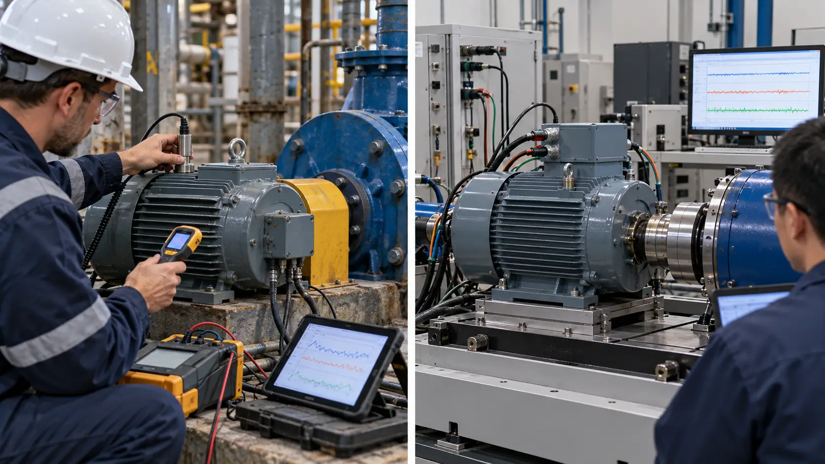
The main value comes from identifying meaningful changes over time. A measurement that remains stable across comparable operating conditions may be more useful than an isolated reading without historical context.
Factory performance testing, by comparison, verifies specified characteristics of a motor before delivery or acceptance. Depending on the requirements, this may include electrical measurements, no-load operation, load testing, temperature-rise assessment, or efficiency determination.
The IEEE 1812-2023 Guide for Testing Permanent Magnet Machines describes methods for determining permanent magnet machine performance characteristics.
The standard also recognizes that the required factory and field testing schedule depends on applicable requirements and contractual specifications.
Therefore, a maintenance technician investigating excessive vibration should not automatically use the same testing program as a manufacturer verifying the rated performance of a new motor.
Safety and Preparation Before Testing
Permanent magnet motor testing should begin with identification, electrical isolation, suitable equipment, and documented test conditions. Inadequate preparation can expose personnel to electrical or mechanical hazards and produce misleading measurements.
Some procedures involve high test voltages or rotating equipment. These should be performed only by qualified personnel following approved procedures and the motor manufacturer’s instructions.
Motor and Drive Isolation Requirements
Before offline electrical testing, the motor must be isolated from its power supply and associated drive equipment in accordance with the applicable procedure.
Permanent magnet motors require particular attention because the rotating permanent magnet field can induce voltage in the stator windings even when external electrical power has been disconnected.
The presence of a variable frequency drive, controller, feedback device, or other connected electronic equipment also affects testing preparation. Applying an insulation tester or other high-voltage test instrument to an improperly connected system may damage sensitive electronic components.
Technicians should follow approved lockout and tagout procedures, verify the electrical state using appropriate instruments, account for stored energy, and prevent unexpected rotation.
Insulation tests also require the winding and test circuit to be safely discharged after testing according to the instrument and equipment instructions.
Electrical isolation does not eliminate every hazard. Rotating shafts, coupled machinery, stored mechanical energy, and permanent magnetic forces may still present risks.
Test Equipment, Operating Conditions and Reference Specifications
Reliable measurements require appropriate instruments and enough technical information to interpret the readings.
Before beginning the inspection, technicians should identify the motor model, rated voltage, power, speed, winding configuration, cooling method, and relevant operating history.
Different tests require different equipment. Insulation resistance tests use insulation resistance testers, winding resistance measurements use suitable resistance instruments, and vibration analysis requires vibration sensors and compatible analysis equipment.
Back-EMF evaluation may require controlled shaft rotation, voltage measurement equipment, and speed recording.
Instrument suitability matters because measurement range, accuracy, calibration status, and connection configuration can affect the results.
Reference information is equally important. A measured value has limited diagnostic significance if the expected result, allowable tolerance, and measurement conditions are unknown.
Whenever possible, obtain manufacturer specifications, previous test reports, and relevant acceptance requirements before performing the inspection.
Electrical and Rotating-Machine Safety Precautions
Testing procedures should be selected according to the motor’s electrical rating, construction, and condition.
High-voltage insulation and surge tests can place additional electrical stress on the winding insulation system. Their suitability should be confirmed before testing, particularly when evaluating older, previously damaged, or recently repaired motors.
Rotating tests require appropriate guarding, secure mounting, and control of the driven equipment. Personnel must also consider the possibility of induced voltage at motor terminals during rotation.
Where testing involves magnet inspection or rotor handling, precautions may be needed for strong magnetic attraction, sensitive instruments, and unsecured ferromagnetic objects.
If the required test cannot be performed safely with the available equipment or expertise, the appropriate action is to arrange qualified technical assessment rather than attempting an improvised procedure.
Electrical Tests for Permanent Magnet Motors
Electrical testing helps assess winding insulation, conductor continuity, phase resistance, and certain winding defects. The most useful method depends on which part of the electrical system is under investigation.
Insulation resistance, polarization index, winding resistance, step voltage, and surge testing measure different characteristics. A normal result from one method should not be interpreted as confirmation that every electrical component is fault-free.
Insulation Resistance Test
An insulation resistance test evaluates the resistance of the insulation between motor windings and ground, or between other specified conductors, under controlled DC test conditions.
The test is useful for identifying possible insulation deterioration, contamination, moisture-related leakage, or other weaknesses affecting the insulation system.
An insulation resistance tester applies an appropriate DC test voltage and measures the resulting resistance. The required voltage and measurement procedure depend on the motor rating, insulation system, and applicable technical instructions.
Temperature is an important variable because insulation resistance can change significantly with winding temperature. Measurements taken under different thermal conditions may therefore require appropriate correction before they can be compared.
A low insulation resistance reading may indicate that further investigation is necessary. However, a satisfactory reading does not rule out winding open circuits, phase resistance imbalance, or all turn-to-turn insulation defects.
The historical IEEE 43-2013 recommended practice covers insulation resistance and polarization index measurement for applicable rotating machinery. IEEE currently classifies this edition as Inactive-Reserved, so its status and the applicable project requirements should be checked before using it as a formal acceptance reference.
Insulation resistance results are most useful when recorded with the test voltage, duration, winding temperature, connection configuration, and appropriate reference criteria.
Polarization Index Test
The polarization index, commonly abbreviated PI, evaluates how measured insulation resistance changes during a specified period of DC voltage application.
The conventional method compares the insulation resistance measured after ten minutes with the value measured after one minute.
PI = Insulation Resistance at 10 Minutes / Insulation Resistance at 1 Minute
This relationship reflects the time-dependent electrical behavior of the insulation system.
During testing, current associated with dielectric absorption may decrease as the insulation responds to the applied voltage. This can cause measured insulation resistance to increase over time.
A change in current is therefore not automatically evidence of insulation deterioration. The important question is whether the measured behavior is consistent with the expected characteristics of the particular insulation system.
PI interpretation depends on insulation materials, winding construction, measurement conditions, and the characteristics of the equipment being tested.
Some insulation systems exhibit limited dielectric absorption, making a conventional PI threshold less useful. Extremely high initial insulation resistance values can also limit the diagnostic value of the ratio.
The Megger insulation testing guidance explains the relationship between time-dependent insulation resistance measurements and insulation condition.
PI should therefore be evaluated together with absolute insulation resistance readings, previous measurements, and the manufacturer’s recommendations rather than treated as a universal pass-or-fail measurement for every permanent magnet motor.
Winding Resistance Test
Winding resistance testing measures the electrical resistance of motor windings and can help identify abnormalities such as poor connections, conductor damage, or unexpected resistance differences.
For a three-phase motor, technicians may compare resistance measurements between the appropriate phase terminals.
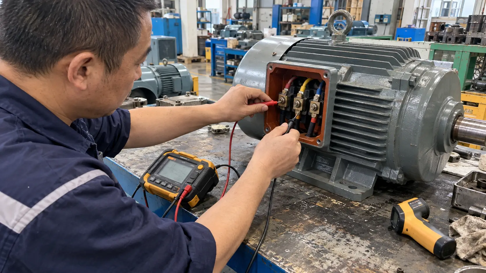
However, the expected relationship depends on the winding configuration and how the terminals are connected. Line-to-line resistance readings are not necessarily identical to individual phase resistance values.
Winding temperature also affects resistance. Copper winding resistance generally increases as temperature increases, which means readings taken at different temperatures should not be compared without considering this effect.
A meaningful assessment uses the correct connection arrangement, suitable measurement equipment, and manufacturer tolerances or comparable reference data.
If one measurement differs unexpectedly, technicians should first confirm the measurement setup and temperature conditions before concluding that the winding is defective.
Winding resistance testing can provide valuable electrical information, but it does not independently confirm insulation integrity or permanent magnet performance.
Step Voltage Test
A DC step voltage test evaluates the response of an insulation system as the applied test voltage increases through controlled stages.
The method can help identify voltage-dependent insulation weaknesses that may not be apparent during a single lower-voltage insulation resistance measurement.
During the procedure, the test voltage is increased according to an approved test plan while leakage current or insulation resistance behavior is monitored.
Unexpected changes in leakage characteristics may indicate the need for further investigation.
However, the results depend on the insulation system, selected voltage levels, test duration, and condition of the winding.
Because this is a potentially stressful electrical test, it should not automatically be included in every permanent magnet motor inspection.
The test should be performed only when its purpose, allowable voltage, potential risks, and acceptance criteria have been established by qualified personnel.
Surge Test
Surge testing is used to investigate turn-to-turn insulation weaknesses within motor windings.
Unlike conventional insulation resistance testing, which primarily evaluates insulation to ground or between specified circuits, surge testing applies controlled voltage pulses to examine winding insulation behavior.
The test equipment records electrical response waveforms, which may be compared with appropriate reference patterns or corresponding winding measurements.
Significant waveform differences can indicate potential winding abnormalities, although the interpretation depends on winding construction, test configuration, and equipment characteristics.
The selected test voltage and procedure must be appropriate for the motor’s insulation system and condition. Improper testing can introduce additional electrical stress.
Surge testing is particularly relevant when investigating suspected interturn insulation defects, but results should be evaluated alongside other electrical measurements and the manufacturer’s acceptance requirements.
Mechanical Tests for Permanent Magnet Motors
Mechanical testing evaluates the physical condition and dynamic behavior of the motor’s rotating components. It is especially useful when a motor develops abnormal vibration, noise, bearing temperature, or signs of mechanical instability.
These symptoms do not always originate inside the motor. Coupled equipment, mounting conditions, shaft alignment, and operating loads can produce similar effects. Mechanical assessment should therefore consider the complete installed system.
Rotor Integrity Inspection
Rotor integrity inspection examines possible physical damage, deformation, loose components, and other structural abnormalities that could affect safe rotation.
Depending on the motor design and accessibility, inspection may involve visual examination, dimensional checks, or suitable nondestructive testing methods.
Surface-mounted permanent magnet rotors may require attention to magnet retention features, while interior permanent magnet rotors have different structural arrangements and inspection limitations.
Not every internal defect can be identified through external inspection. Some conditions require specialized equipment or partial disassembly.
Warning signs may include abnormal vibration, visible damage, unusual mechanical noise, or evidence of contact between rotating and stationary components.
If rotor damage is suspected, continued operation should be evaluated against the potential consequences of further mechanical failure. The rotor should not be subjected to additional high-speed testing without an appropriate safety assessment.
Vibration Spectrum Analysis
Vibration analysis measures motor vibration and examines its frequency characteristics to help identify possible mechanical or electromagnetic abnormalities.
Common causes of excessive vibration include rotor imbalance, shaft misalignment, bearing defects, structural looseness, and operating conditions that excite mechanical resonance.
Vibration sensors measure the motor’s response at selected locations. Frequency analysis, often using a Fast Fourier Transform, separates the measured vibration signal into frequency components.
Different frequency patterns may suggest different fault mechanisms. However, a particular frequency peak does not automatically identify a unique cause.
The interpretation depends on running speed, load, sensor position, mounting arrangement, and the mechanical characteristics of the complete installation.
For example, increased vibration near rotational frequency may justify checking imbalance or alignment, but additional evidence is needed to distinguish between these possibilities.
Historical comparison can be particularly valuable. A vibration increase measured under comparable operating conditions may indicate developing problems even when a single absolute measurement does not provide a clear diagnosis.
Where formal vibration limits are required, technicians must select standards applicable to the motor and its testing conditions.
Shaft Alignment and Bearing Condition Checks
Shaft alignment and bearing condition directly affect mechanical reliability.
Misalignment between a motor and its driven equipment can increase mechanical loading, vibration, and coupling stress. Suitable alignment instruments can help verify the relative positions of connected shafts.
This process should not be confused with checking the position of permanent magnets inside a rotor. Shaft alignment and magnet placement are separate technical concerns requiring different inspection methods.
Bearing assessment may involve vibration measurements, temperature monitoring, acoustic information, lubrication inspection, and examination of operating history.
Abnormal bearing temperature does not necessarily indicate bearing damage. Excessive load, unsuitable lubrication, installation problems, and ambient conditions can also influence temperature.
A reliable conclusion should therefore consider several measurements rather than one isolated symptom.
Where mechanical problems are confirmed, corrective actions may involve alignment adjustment, lubrication correction, bearing replacement, or further structural inspection.
Magnetic Tests for Permanent Magnet Motors
Magnetic testing evaluates characteristics associated with the permanent magnets and their interaction with the electrical windings. It is particularly relevant when a motor exhibits unexplained torque changes, unusual back-EMF characteristics, or suspected magnet damage.
Because permanent magnet performance depends on magnet material, temperature, magnetic circuit geometry, and operating conditions, magnetic measurements must be interpreted against a suitable reference.
Magnetic Field Strength and Flux Distribution Assessment
Magnetic field assessment measures the strength or distribution of a magnetic field at defined locations.
Depending on the motor configuration, engineers may use Hall-effect probes, gaussmeters, magnetometers, or specialized magnetic measurement systems.
These measurements can help identify possible magnetic irregularities or differences from expected field patterns.
However, results are strongly influenced by measurement position, probe orientation, air gap geometry, magnetic circuit construction, and temperature.
A field reading taken near an accessible rotor surface cannot automatically be compared with a reading from a different rotor design or measurement location.
The same consideration applies when comparing motors with different magnet arrangements, including surface-mounted and interior permanent magnet configurations.
Magnetic field testing is most meaningful when the measurement geometry and operating conditions are repeatable and supported by an appropriate design or historical reference.
Back-EMF Testing and Result Interpretation
Back electromotive force, or Back-EMF, is the voltage induced in motor windings when the permanent magnet rotor rotates.
For a permanent magnet synchronous motor, measuring this induced voltage under controlled conditions can provide information about magnetic flux linkage and the electrical characteristics of the machine.
One conventional approach involves rotating the motor at a known speed while measuring the induced voltage and recording the waveform.
The measurement configuration must be documented. For example, line-to-line voltage and phase voltage are not interchangeable, and RMS values cannot automatically be treated as peak values.
Rotational speed is another critical variable.
For a given motor operating under comparable conditions, back-EMF magnitude is related to rotational speed. Consequently, two measurements taken at different speeds cannot be compared directly without accounting for that difference.
Waveform shape also matters. Motors may have sinusoidal or nonsinusoidal induced voltage characteristics depending on their design. A simple overall RMS comparison may therefore be insufficient for certain diagnostic purposes.
The HBK technical article on permanent magnet motor Back-EMF measurement explains how controlled speed measurements, voltage waveforms, and suitable signal processing can be used to evaluate back-EMF characteristics.
When examining an existing motor, technicians should compare results with suitable manufacturer data or historical measurements taken under equivalent conditions.
An unexpected voltage difference or waveform distortion may justify further investigation. However, it does not independently prove permanent magnet demagnetization because electrical connection differences, winding abnormalities, speed variation, and measurement errors can also influence the result.
Back-EMF testing should therefore form part of a broader diagnostic assessment when magnetic performance problems are suspected.
Identifying Possible Demagnetization and Magnetic Performance Changes
Permanent magnet demagnetization occurs when a magnet loses part of its magnetization.
The extent and reversibility of the change depend on the magnetic material, temperature, applied magnetic fields, and the magnet’s operating point.
Excessive temperature and unfavorable magnetic conditions can contribute to irreversible loss of magnetic performance under certain circumstances.
In a motor, reduced effective magnet flux may influence back-EMF, torque production, current requirements, and operating behavior.
However, similar symptoms can result from other problems. Reduced torque, for example, may also be associated with current limitations, incorrect control settings, thermal protection, or mechanical loading.
A sound diagnostic approach therefore combines magnetic-related measurements with electrical, thermal, and operating information.
If magnetic degradation is suspected, the next step is to compare measurements with reference specifications and determine whether further controlled testing or specialist inspection is necessary.
Testing Standards, Acceptance Criteria and Result Interpretation
Permanent magnet motor testing results should be evaluated against criteria appropriate to the motor and the purpose of the inspection. A measurement is not automatically acceptable simply because it falls within a commonly published range.
The relevant standard, manufacturer specification, historical baseline, and agreed project requirements determine how the result should be interpreted.
Applicable IEEE and IEC Motor Testing Standards
Different standards address different aspects of rotating electrical machines. Some cover performance measurement, others describe insulation testing or define vibration testing conditions.
The following references provide a starting point for identifying suitable requirements.
| Standard | Main Scope | Relevance to Motor Testing |
|---|---|---|
| IEEE 1812-2023 | Testing permanent magnet machines | Performance characteristics and measurement methods |
| IEEE 43-2013 | Insulation resistance and polarization index | Historical guidance for applicable winding insulation tests |
| IEC 60034-1:2026 | Rating and performance of rotating machines | Rated characteristics and applicable performance requirements |
| IEC 60034-2-1:2024 | Determination of losses and efficiency | Efficiency and loss measurement for machines within its scope |
| IEC 60034-14:2018 | Mechanical vibration testing | Factory vibration procedures and limits for specified machines |
These standards do not all serve the same purpose.
IEEE 1812-2023 provides general guidance for measuring permanent magnet machine performance characteristics. It does not require every motor to undergo every available test.
IEC 60034-1:2026 addresses ratings and performance requirements for rotating electrical machines within its scope.
IEC 60034-2-1:2024 describes methods for determining motor losses and efficiency under applicable conditions.
IEC 60034-14:2018 defines factory vibration testing requirements for certain machines under specified conditions. Its limits should not automatically be applied to every installed motor operating under load.
The suitability of any standard must be checked against its scope, the motor design, the required test, and contractual or regulatory requirements.
How to Establish Test Acceptance Criteria?
Acceptance criteria define whether a measurement satisfies the requirements of a particular motor or inspection objective.
These criteria should be established before testing whenever practical.
For insulation resistance, acceptance may depend on motor rating, insulation type, winding temperature, and applicable guidance.
For winding resistance, evaluation may involve expected resistance values, temperature correction, and allowable differences between corresponding measurements.
For vibration testing, the applicable limits may depend on the motor’s size, speed, mounting arrangement, and whether testing occurs under factory or installed conditions.
Back-EMF testing requires appropriate reference information concerning speed, voltage measurement configuration, temperature, and expected waveform characteristics.
When reliable reference values are unavailable, it may be possible to identify an abnormal trend without making a definitive acceptance decision.
A test report should distinguish between a measured result, an observed deviation, and a confirmed failure.
This distinction helps prevent unnecessary replacement decisions and reduces the risk of overlooking faults that require further investigation.
Essential Information in a Motor Test Report
A test report should contain enough information for another qualified engineer to understand how the measurement was obtained and whether the comparison is valid.
At a minimum, the record should identify the tested motor, the test method, instrument details, relevant conditions, measured values, and the criteria used for evaluation.
For electrical measurements, important information may include test voltage, winding temperature, measurement duration, and terminal connections.
For vibration analysis, the report should identify sensor locations, running speed, load condition, measurement direction, and relevant frequency or amplitude data.
For Back-EMF testing, the report should record rotational speed, voltage measurement configuration, waveform information, temperature when relevant, and the reference used for comparison.
Including this information makes the results more useful for maintenance trending, technical review, and future project decisions.
When Do Test Results Require Further Investigation?
Additional investigation is appropriate when a result exceeds an applicable limit, differs unexpectedly from the reference condition, or conflicts with other available evidence.
However, a questionable reading does not always indicate a defective motor.
Before deciding on corrective action, technicians should examine possible measurement errors, instrument configuration, environmental influences, and operating differences.
For example, a change in insulation resistance may be affected by winding temperature. A vibration increase may result from a different load or mounting condition. A Back-EMF difference may be caused by unequal rotational speeds or voltage measurement configurations.
If the deviation remains after these factors have been considered, further testing may be justified.
For safety-critical abnormalities, operation should follow the relevant safety procedures and qualified engineering assessment rather than relying on a single acceptable measurement from another test.
How to Discuss Permanent Magnet Motor Test Requirements With Hiest
For a new permanent magnet motor project, testing requirements should be discussed alongside the motor’s intended application and technical specifications.
Hiest provides permanent magnet motor solutions for industrial applications. Customers evaluating a motor project can use the testing principles described in this guide to identify relevant verification requirements and clarify what technical information should be requested before placing an order.

Which Hiest Motor Specifications Affect Testing Requirements?
The motor’s rated specifications and construction influence both the necessary testing methods and the conditions under which measurements should be performed.
Hiest offers industrial permanent magnet motor configurations, including three-phase permanent magnet synchronous motors and water-cooled motor options.
For a motor selected for continuous industrial operation, relevant requirements may include rated power, torque, operating speed, supply voltage, duty cycle, and cooling conditions.
These specifications help define the expected operating environment and determine which measurements are relevant.
For example, cooling conditions may affect temperature-related assessment, while rated speed and winding configuration influence the interpretation of electrical and Back-EMF measurements.
The exact testing scope should be confirmed for the selected motor model rather than assumed from the product category.
What Test Reports or Verification Documents Should Buyers Request?
The most useful test documents are those directly related to the intended application and specified acceptance requirements.
For some projects, this may involve electrical measurements, motor performance information, or verification of particular operating characteristics.
For other applications, customers may require additional documentation covering vibration, temperature, efficiency, or specified performance conditions.
Before requesting documentation, it is useful to distinguish between product specifications, routine inspection records, type-test results, and tests specifically required for the project.
These documents have different purposes and should not be treated as interchangeable.
Customers considering a Hiest permanent magnet motor can identify the required documents during technical discussions and confirm which records, testing arrangements, and verification options are available for the selected model.
Where special testing is necessary, the required procedure, acceptance criteria, documentation format, and any commercial implications should be agreed upon before the order is finalized.
How to Submit Your Application and Testing Requirements to Hiest?
A clear technical inquiry helps establish whether a motor configuration and the requested verification requirements are appropriate for the project.
Customers should provide the intended application, motor power and speed requirements, voltage, duty cycle, cooling conditions, and relevant environmental information.
If the motor is intended to replace existing equipment, the current motor nameplate details and known operating problems may also be useful.
Testing requirements should be stated separately from general product specifications. For example, a customer may need confirmation of a particular performance characteristic or additional inspection documentation.
Hiest can review the submitted application information and discuss the appropriate product direction and next technical steps.
Clear technical communication helps ensure that motor selection, testing expectations, and acceptance requirements are addressed before the project advances.
Permanent Magnet Motor Testing Checklist and Next Steps
A useful permanent magnet motor testing program should end with a documented decision rather than simply a collection of readings.
The test results should indicate whether the measured conditions are acceptable, whether additional inspection is required, or whether maintenance and corrective action should be considered.
Pre-Test Inspection and Documentation Checklist
Before starting a motor inspection, confirm the essential technical information and testing arrangements.
- Identify the motor type, model, rated voltage, power, speed, and winding configuration.
- Define the purpose of testing and the suspected problems, if any.
- Review applicable manufacturer instructions and technical standards.
- Confirm electrical isolation, rotating equipment safety, and suitable test equipment.
- Identify measurement conditions, reference values, and acceptance criteria.
- Record instrument details, test connections, operating conditions, and measured results.
- Document abnormalities, limitations, and recommended follow-up actions.
This checklist provides a basic framework, but it does not replace a qualified test procedure developed for the particular motor and installation.
How to Decide Whether to Retest, Repair or Replace a Motor?
The appropriate next step depends on the severity of the observed condition, the reliability of the measurement, and the consequences of continued operation.
If test results appear inconsistent because of uncertain measurement conditions, repeating the test under controlled and comparable conditions may be appropriate.
If an abnormality is confirmed but the underlying cause remains uncertain, additional diagnostic testing should be considered before making a repair or replacement decision.
Where testing identifies a correctable issue, such as an alignment problem or a condition requiring maintenance, the selected corrective action should be followed by appropriate verification.
If serious winding damage, rotor defects, or irreversible magnetic deterioration is confirmed, repair feasibility and replacement requirements should be evaluated based on the motor design, safety implications, and operational needs.
Not every abnormal result justifies immediate replacement, and not every acceptable measurement proves that the motor is safe for continued operation.
The final decision should reflect the complete technical evidence, the manufacturer’s requirements, and the assessment of qualified personnel.
Conclusion
Permanent magnet motor testing provides important information about electrical insulation, winding condition, rotor integrity, vibration behavior, and magnetic performance.
The main testing methods serve different purposes. Insulation resistance testing evaluates aspects of winding insulation, surge testing investigates possible interturn insulation weaknesses, vibration analysis supports mechanical fault diagnosis, and Back-EMF measurement can provide information about permanent magnet and winding characteristics under controlled conditions.
Reliable interpretation depends on selecting the correct test, documenting measurement conditions, and comparing results against suitable specifications or historical references.
For maintenance applications, testing should help determine whether a motor requires further inspection, corrective maintenance, or replacement assessment. For new motor projects, the required verification methods and acceptance criteria should be agreed upon before testing or procurement.
The most effective approach is not to perform every available test, but to select the measurements that directly address the motor’s condition and the decision that needs to be made.
By combining appropriate testing methods with clear technical documentation, operators and engineers can make better-informed decisions about permanent magnet motor reliability, maintenance, and performance verification.