
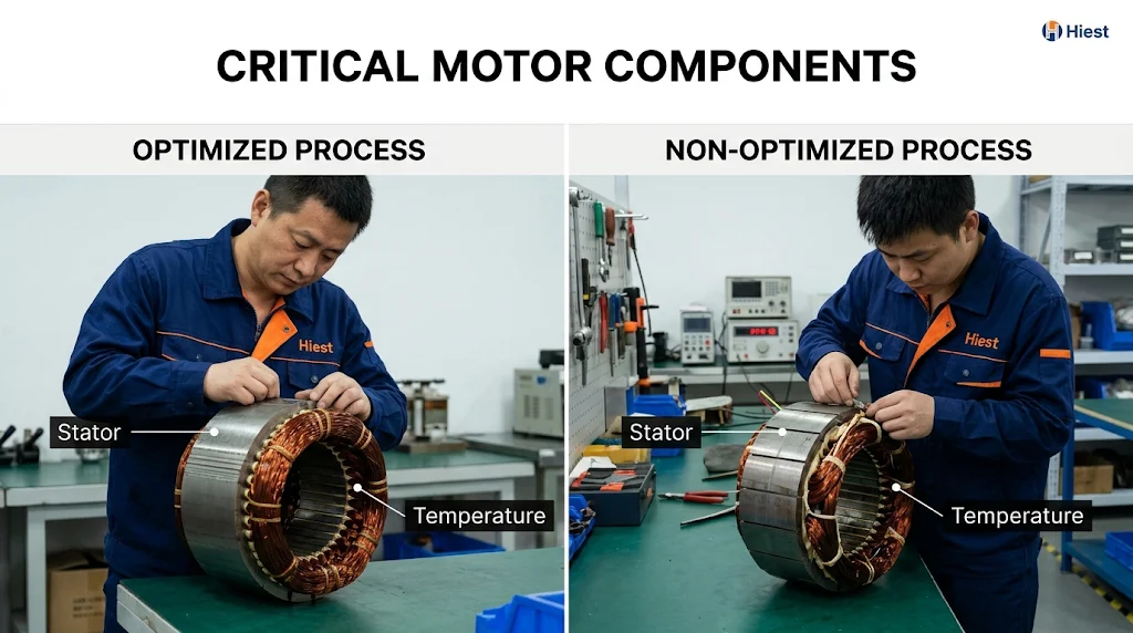
A PMSM stator is built by three process chains, and the relationship between them is the subject of this article. Lamination and stacking establish the magnetic circuit and the mechanical datum. Winding establishes the electromagnetic conversion performed by the stator windings, and the insulation that surrounds them inside the slot. Impregnation and curing bind the insulation system into one body and create the thermal path out of the conductor. The chains are not independent work packages. Each one hands a geometry to the next, and that geometry constrains what the next operation can achieve.
The consequence is that stator quality cannot be read from the finished specification. Two stators with the same turns, the same steel and the same slot dimensions can differ in core loss, void content and end winding stiffness, entirely because of how the three operations were run. Those differences are the reason a buyer who wants to compare suppliers has to look at process information rather than at finished part parameters alone.
This article explains what each chain decides, where the chains meet, and what evidence a buyer can reasonably ask for. It stays at the level of process mechanism and decision conditions. It does not give tolerances, equipment models or proprietary parameters, and it does not cover rotor magnet assembly, complete motor testing or commercial terms.
Critical Inputs Before PMSM Stator Manufacturing Begins
Before a stator route can be selected, several conditions have to be fixed, because they determine which process options are even feasible. The first is electrical duty, which covers the voltage the insulation must withstand, the current the conductor must carry, the fundamental frequency and the switching characteristics of the supply. The second is the insulation system type, which has to be chosen against that duty rather than against a general preference. The third is the thermal requirement, which sets how much heat has to leave through the stator and therefore how much the impregnation and cooling paths matter. The fourth is the mechanical envelope and the production volume, which together constrain the tooling and the degree of automation that make sense.
These inputs are design decisions, and they sit upstream of process selection. A stator whose electrical duty has not been fixed cannot be matched to an insulation system, and an insulation system that has not been chosen cannot be matched to an impregnation method. Treating these as later details is what produces a process route that has to be revised after the first prototype. At higher operating speeds the mechanical and thermal demands on the stator change as well, and the requirements for custom PMSM designs in higher speed ranges are set by the same inputs.
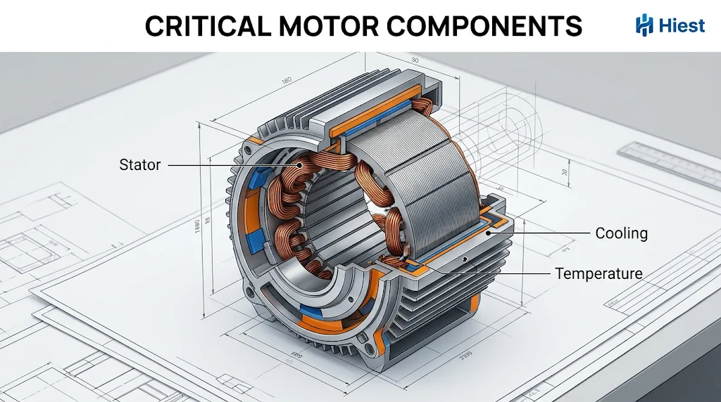
The manufacturing conditions form a second set, and they are the ones a buyer can actually confirm. For each chain there are conditions that must be defined rather than discovered, including the stacking method and pressure, the winding pattern and slot fill target, the insulation configuration, the impregnation method and the curing profile. None of these is visible in the finished part, and all of them are decided before production starts.
Why Stator Manufacturing Quality Matters for PMSM Performance?
Stator losses have to be attributed carefully, because they are not purely a manufacturing outcome. Core losses depend on the magnetic properties of the steel, on the flux density the design operates at, on the frequency and waveform of the supply, and on manufacturing effects such as stamping damage and interlamination short circuits. Winding losses depend on current, on conductor resistance, on operating temperature and on additional AC effects where they are relevant, including skin and proximity effects at higher frequencies and in the end winding region. Manufacturing decisions influence all of these, but their final magnitude must be evaluated under the intended electromagnetic and operating conditions.
That distinction matters for how the process is judged. A core built from good steel on a worn die can still show elevated loss, because the burr and the interlamination contact are part of the loss mechanism rather than cosmetic defects. A winding with the correct turns and conductor can still show higher loss than expected if the end windings are longer than the design assumed. In both cases the fault is real, and in neither case can the size of the effect be stated without measurement under the actual operating conditions.
The relevant test methods are defined rather than improvised. IEC 60034-2-1:2024 provides methods for determining losses and efficiency in rotating electrical machines, and IEC 60034-1:2026 gives the general requirements for rating and performance. Their applicability to a specific machine has to be confirmed against the machine type, the supply conditions and the target market, and citing a standard is not evidence that a manufacturer conforms to it. For converter fed PMSM applications, IEC 60034-2-3:2024 should also be considered when determining the applicable loss and efficiency test procedure. The selected method must match the motor supply and operating conditions.
Three paths carry stator process into motor behaviour. The magnetic path runs through the steel grade, the stacking pressure, the burr condition and the interlamination coating. The electrical path runs through the winding pattern, the slot fill and the end winding length. The thermal and insulation path runs through the slot insulation, the completeness of resin filling and the degree of cure. On the same motor these paths add together, and the boundary is that the stator is one part of a system. The rotor, stator and power supply interact in ways that a stator specification alone cannot describe.
Lamination, Core Steel, Stamping, and Stacking
Stamping is often treated as a cutting operation. It is not. Within the wider sequence that runs from stamping winding and assembly to final test, it is the step that fixes both the loss behaviour of the core and the datum that later operations depend on. The stamped lamination simultaneously determines how much loss the core will produce, whether the laminations remain insulated from one another after stacking, and what mechanical datum the rest of the build will reference. A lamination that is dimensionally correct but has a poor edge condition is a magnetic problem and an insulation problem at the same time.
The section separates the three confirmable inputs. Core steel grade and thickness set the baseline. Stamping quality, meaning burr, coating and die condition, determines whether that baseline survives into the stack. Stacking method determines how the individual laminations become a core, and at what cost in stiffness, interlamination contact and additional loss.
Core Steel Grade and Thickness, What the Choice Changes
Grade and thickness act on two different loss mechanisms, and this is why a single number cannot describe a steel. Thickness controls the path available to eddy currents, so a thinner sheet reduces the eddy current contribution. The alloy system, and in particular how much silicon is present, raises resistivity and shifts the hysteresis behaviour. The two effects do not point in the same direction for every property. A choice that reduces loss can also reduce the flux density the core can carry, which means more turns or a longer core for the same torque, and either of those changes the winding loss.
The second consequence is manufacturability. Thinner or harder material is more demanding to stamp cleanly and more demanding to stack tightly. Burr formation and die wear behave differently, and the flatness achieved during stacking changes. A material selected purely on a loss curve may therefore arrive at the press with a narrower process window than the project assumed.
The practical conclusion is that material selection has three dimensions. The loss direction is the first. The flux density the design needs is the second. The process window that the die and the stacking method can hold is the third. All three should be confirmed against supplier data for the specific material and against the manufacturer’s own process conditions, because a data sheet describes the steel and not the stack.
Stamping Quality, Burrs, Insulation Coating, and Die Condition
A burr is a magnetic defect before it is a cosmetic one. When laminations are stacked and compressed, a burr on one sheet can press through or bridge the coating on the adjacent sheet, creating an electrical path between laminations that was not intended. Once that path exists, the eddy current loops are no longer confined to individual sheets, and the effective loss of the core can rise. The change is not necessarily visible in a terminal measurement, because the effect is distributed through the core rather than concentrated at one point.
The coating is the component that carries interlamination insulation, so its integrity is a process variable in its own right. Coating type, coating thickness and how the coating survives the stamping shear all matter, and the condition is not fixed once it has been set. Die edge wear accumulates with stroke count, so burr height and dimensional consistency drift with production volume. That drift is why stamping quality is a monitored condition rather than a one time qualification.
Finished core or motor level tests may reveal the effects of manufacturing defects, but they do not necessarily identify the underlying process cause. Process records, suitable core level measurements and final inspection results should be evaluated together, because each of them answers a different question about the same core.
Stacking Methods and Their Effect on Core Stiffness and Loss
Stacking converts a pile of laminations into a structural core, and every method for doing it trades one property against another. Interlocking, welding, bonding and mechanical fastening differ in connection strength, in how much interlamination contact they create, and in whether they introduce local stress or an additional conductive path. A method that produces a stiff core suitable for later machining may also create localized shorting between laminations. A method that preserves interlamination insulation may produce a core that is less rigid.
Pressure is the second variable and it acts on the same balance. Higher pressure closes the gaps between laminations, which improves the stacking factor and the mechanical integrity, and it also raises the probability that burrs and coating defects make contact. The result is not a monotonic improvement. There is a working range, and that range depends on the material, on the coating and on the die condition.
The third consequence is transmission. Whatever stiffness and datum the stack ends up with is what the winding operation receives. A core that is not square, or whose bore is not aligned with the mounting face, makes insertion harder and makes the end winding geometry less predictable. The same datum error propagates to the air gap when the rotor is fitted.
Winding, Coil Winding, Insertion, and End Winding Forming
Winding places a specified number of turns of a specified conductor into a slot whose area is fixed, maintains a specified insulation configuration, and produces an end winding that will survive the electromagnetic forces of operation. The rotating field that the stator windings produce depends on how those turns are arranged and how the phases are distributed, which is why the three parts of that task are separate. The winding pattern sets the end winding geometry. The insertion process determines how much insulation space is preserved and how much void is left in the slot. The forming and connection of the ends determine stiffness, vibration response and the stability of the joint resistance.
The result cannot be inferred from the finished specification. Slot fill, insulation reliability and end winding rigidity are outcomes of the process rather than properties of the design, which is why confirmation has to happen at the process level rather than at the drawing level.
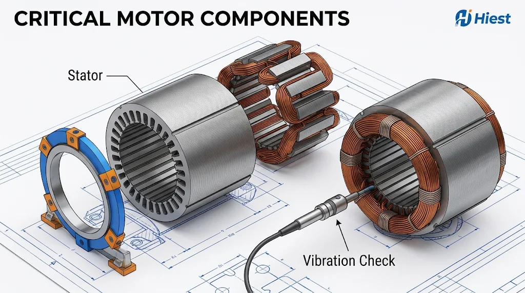
Winding Pattern and Its Effect on End Winding Length and Copper Loss
The winding pattern decides the coil span, and the span decides how much conductor sits outside the core. Concentrated windings keep the end turns short and compact. Distributed windings spread the conductors over a wider span and produce a longer end winding geometry. Neither pattern is better in general. The difference that matters here is geometric, and it carries a direct electrical consequence.
Longer end windings mean more conductor length for the same number of turns, and more conductor length means more resistance for the same cross section. At a given current the winding loss therefore moves in the same direction as the end winding length. This is a directional relationship, not a fixed ratio, and the actual magnitude depends on the design and on the operating point.
The third consideration is process complexity. Span and distribution change what the winding machine has to do, how difficult insertion becomes, and what equipment the operation requires. A pattern that offers a shorter end winding may demand a different tooling set and a different cycle time, so selecting a pattern on end winding length alone ignores the constraint that will decide whether the design can be produced at the required rate.
Slot Fill, Insulation Space, and Insertion Constraints
Increasing copper slot fill places greater demands on conductor arrangement, insertion clearance, insulation geometry and impregnation access. Higher fill can be achieved through changes in conductor size, shape or packing arrangement, and it does not necessarily require reducing insulation thickness. The practical limit depends on the winding design, the insulation requirements and the manufacturing capability.
The terminology matters here, because slot fill is not a single quantity. Copper slot fill, wire slot fill including the conductor insulation, and the fill of the available winding area are different measures with different values for the same stator, and a quotation that states a target without defining which measure it refers to cannot be compared with another. The definition should be agreed before the number is discussed.
Insertion is where the design trade becomes visible. Whether the winding is placed by hand or by machine, the conductor has to pass into a slot lined with insulation, and the process exerts force and friction on that lining. Insulation damage or displacement during insertion may create local defects, including voids in some cases. Other forms of damage can compromise dielectric integrity without necessarily creating a void. Whether any of these leads to partial discharge depends on the insulation system, the applied voltage waveform, the local geometry and the operating conditions, so the risk has to be evaluated against the intended electrical duty rather than inferred from the presence of a defect alone.
Consistency is the last variable. Automated insertion can improve process repeatability when tooling, machine settings and process controls are properly established. Manual insertion may also achieve acceptable and repeatable results under suitable procedures and inspection controls. The appropriate method should be selected according to winding geometry, production volume, quality requirements and demonstrated process capability, because what the buyer is comparing is capability evidence rather than a label.
End Winding Forming, Bracing, and Connection
The end winding is the part of the winding that carries current and is not supported by steel. Forming determines its shape, and shape determines how it responds to the electromagnetic forces that act on it every cycle. A well formed end winding has a defined geometry that can be braced and that leaves a predictable path for resin to penetrate later.
Bracing is what converts shape into stiffness. The bracing material and the method of applying it determine how much relative movement the end winding can undergo under load. Insufficient bracing allows movement, movement produces abrasion against adjacent insulation, and abrasion over time removes the insulation margin the design assumed. The effect is progressive, which is exactly why it is easy to defer and expensive to discover late.
Connection is a separate reliability item and should be treated as one. The joint between the winding and the lead, or between phase sections, carries the full current through a small contact area, and its resistance determines the local temperature rise at the joint. A joint that is electrically acceptable when new can drift if the process is not controlled, and the drift appears as a hot spot rather than as a winding failure.
The end winding also sets up the next operation. The shape that forming produces and the gaps that bracing leaves are the geometry that impregnation has to fill. This is the first place where the winding chain and the impregnation chain have to be considered together rather than in sequence.
Varnish, Impregnation, Curing, and Insulation Integrity
Impregnation is not a surface treatment. It is the operation that turns a collection of insulated conductors, slot liners and a steel core into a single electrical and thermal body. Its inputs are the void geometry produced by stamping and by winding. Properly controlled impregnation can fill accessible voids, improve mechanical support within the winding assembly, and reduce thermal resistance along relevant heat transfer paths. The actual results depend on the resin system, the winding geometry, the impregnation method and the process validation.
Judging impregnation by appearance is the most common error in this part of the process. A stator with a glossy, evenly coated exterior can still contain unfilled voids deep in the slot, and cure degree is even less visible than fill. Resin that has not fully cross linked looks the same on the day of manufacture as resin that has, and the difference appears later as reduced mechanical strength and reduced thermal endurance. This is why the discussion that follows separates the impregnation method, the resin system and the curing profile rather than treating varnish as one variable.
Impregnation Method and Resin System, What the Choice Changes
Trickle impregnation relies on gravity and capillary action to draw resin into the winding from the end. It is a comparatively simple process with a short cycle, and its filling consistency depends on how well the resin flow is controlled relative to the geometry it has to penetrate. In a shallow slot with a simple end winding the path is short and the method can be adequate. In a deep slot with a complex end winding, the resin has further to travel and more opportunities to stop before it reaches the bottom of the slot.
Vacuum impregnation, including the pressure assisted variant, changes the driving mechanism. The air in the voids is removed first, and resin is then introduced into a reduced pressure environment where the pressure difference and capillary action together carry it into passages that would otherwise trap air. That is why the method is described as having greater filling capability for deep slots and complex end geometries. The cost is on the equipment side, because vacuum vessels, handling and cycle time all add complexity.
The resin system has to match the method rather than being selected independently. A resin has a working life during which it remains flowable, and filling has to be complete before that window closes. If the resin gels while it is still travelling, the result is a partially filled slot with resin in the wrong places. Viscosity, gel behaviour and the reaction characteristics of the system all interact with the geometry and with the method, which is why the two are specified together.
Curing Profile and Insulation Integrity
The appropriate curing profile depends on the resin chemistry, the component thermal mass and validated processing conditions. It is not transferable between resin systems, and it is not reducible to a single rule about heating slowly.
Excessive heating rates may create temperature gradients between the surface and the interior, uneven cure across the winding, trapped volatiles in those resin systems where volatile release is part of the process, and additional residual stress on cooling. The relative importance of these effects differs between solvent containing and solvent free systems and between thin and massive parts, which is why the mechanism cannot be generalized from one material to all of them.
The hold stage determines the degree of cross linking. A hold that is too short leaves the resin incompletely cured, with lower mechanical strength and lower thermal endurance than the system was selected for. A hold that is longer than necessary adds cycle time and exposes the insulation to additional thermal history. The cooling arrangement affects residual stress, and the way parts are loaded affects how uniformly the furnace treats them, so two stators in the same batch at different positions can see different thermal histories.
The ramp, hold and cooling stages should therefore be defined using the resin supplier requirements and verified for the actual stator geometry and loading arrangement, rather than adopted from a generic recommendation.
How Impregnation Links Winding, Core, and Thermal Path
The mechanical function of cured resin is to limit relative movement. Every current cycle produces an electromagnetic force on the winding, and the end winding is where that force produces the largest displacement. Resin that penetrates the end winding and bonds it to the core converts a free vibrating structure into a restrained one. The benefit is not the elimination of vibration, it is the reduction of relative movement between conductors and between the winding and the core, which is what drives abrasion and loosening over time.
The thermal function is the one most often underestimated. Air is a far poorer conductor than resin or insulation material, so an unfilled void in the slot sits in the heat path as a local resistance. In many conventional stators, a substantial portion of the heat generated in slot conductors passes through the insulation system toward the stator core and housing. End winding heat may also be removed through direct air or liquid cooling. The thermal effect of an unfilled void therefore depends on its location, on the surrounding materials and on the cooling architecture of the motor.
The electrical function follows from the same geometry. Voids within an insulation system can alter the local electric field distribution and may contribute to partial discharge under sufficiently high electrical stress. Whether partial discharge occurs depends on the insulation system, the applied voltage waveform, the local geometry and the operating conditions, so the risk should be evaluated against the intended electrical duty rather than inferred from void presence alone. For inverter driven machines this evaluation is a design question in its own right, and the applicable framework depends on the insulation system type and on the voltage stress the winding will actually see.
None of these three functions can compensate for the geometry the earlier chains produced. Resin fills the voids that exist, it does not create space that the slot and the winding did not leave. Impregnation completes the insulation system, it does not correct the winding.
How the Three Processes Interact in Stator Quality?
The three chains form a sequence in which each output becomes the next input. The dependency can be stated compactly.
| Chain | What it produces | What consumes it |
|---|---|---|
| Lamination and stacking | Slot form, reference faces, interlamination condition | Winding and insertion |
| Winding and forming | Void structure inside the slot, end winding shape | Impregnation |
| Impregnation and curing | Bonded winding and core, thermal path, insulation integrity | Testing and service |
Deviations introduced during lamination can affect the winding and impregnation processes downstream. Some may be detected and corrected through defined rework procedures, while others may require rejection or a change to the manufacturing process. Downstream operations should not be assumed to compensate for upstream deviations without verification.
The trade-offs cross the chain boundaries, which is why single process optimization fails. Raising copper slot fill improves the use of the slot area and increases the demands on insertion and on impregnation access, so a decision taken in the winding chain changes the difficulty of the impregnation chain. Increasing stacking pressure improves stiffness and reduces the gap between laminations, and it also raises the probability that a burr will bridge the coating. A stronger bond between the winding and the core improves vibration behaviour and can complicate later rework. None of these trades can be evaluated inside a single operation.
The practical consequence is that process capability should be discussed as a combination. A manufacturer who describes a stacking method, a winding pattern and an impregnation method separately is describing three options. The question a buyer needs answered is how those three are configured together, what the interfaces between them are, and how the combination is verified. That is a different question from which individual technique sounds most advanced.
How Buyers Verify Stator Manufacturing in a PMSM Project?
Verification has to happen at the process level, because the finished stator does not disclose how it was made. A sample that passes an electrical test and looks correct can come from a process whose die is worn, whose insulation insertion is inconsistent, or whose cure is incomplete. None of those conditions is visible in the finished part on the day of acceptance, and all of them affect the population rather than the sample.
The evidence to request falls into three layers, and keeping them separate is what makes two quotations comparable.
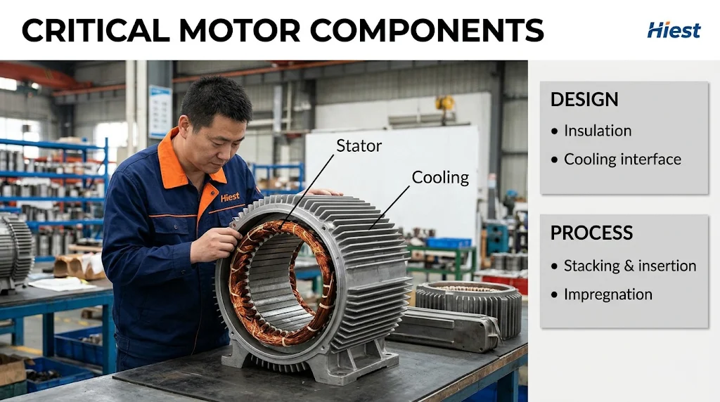
Design requirements. What the drawing and the specification require of the stator, including the electrical duty, the insulation system, the winding scheme, the cooling interface and the applicable standards with their versions. This layer answers what the stator has to do.
Process controls. What the manufacturer’s own process documents set as the operating range and how that range is held, including the key process parameters, the control method, the sampling arrangement and the record of process changes. This layer answers how the manufacturer intends to keep the requirement stable.
Inspection evidence. What was actually measured, on what sample, under what conditions, against what limit, and with what traceability. This layer answers whether the intended condition was achieved in production rather than only in qualification.
Applied to the three chains, the request takes a predictable form.
For lamination, the design requirement is the core steel grade, the thickness, the lamination geometry and the interlamination insulation specification. The process control items are the burr control method, the die maintenance and sharpening regime, the stacking method and the pressure conditions, and the sampling arrangement for stack dimensions. The inspection evidence items are the coating condition after stamping, the burr measurement records, the stack dimension and squareness results, and whatever core loss measurement the process uses.
For winding, the design requirement is the winding pattern, the turns, the conductor specification, the slot and phase insulation configuration, and the definition of the slot fill measure being used. The process control items are the insertion method with its settings, the tension control, the bracing method and material, and the connection method. The inspection evidence items are the slot fill result against the agreed definition, the insulation configuration check, the winding resistance and balance results, and the joint inspection records.
For impregnation, the design requirement is the insulation system, the impregnation method and the resin system specified for that duty. The process control items are the resin handling conditions, the vacuum and pressure conditions where applicable, the curing profile and the loading arrangement. The inspection evidence items are the cure verification method the manufacturer uses, the resin batch records, the fill inspection method, and the electrical tests applied after impregnation.
For the insulation system as a whole, the applicable framework depends on the duty. IEC 60034-18-41:2014+AMD1:2019 provides qualification and quality control requirements for Type I insulation systems used in machines fed from voltage converters, and IEC 60034-18-42:2017+AMD1:2020 addresses Type II systems that are expected to withstand partial discharge. IEC 60034-27-1:2017 covers offline partial discharge measurement on the winding insulation of rotating electrical machines where that measurement is appropriate. Which of these applies, and whether measurement, qualification or both are required, depends on the voltage class, the insulation type and the supply, and it should be determined for the project rather than assumed.
Two conditions decide whether any of this produces a usable comparison. The first is that inspection items and their applicable standards are named with their versions, because a requirement without a version is not a specification. The second is that the comparison conditions themselves are written into the technical agreement, so that two suppliers are being asked about the same material family, the same insulation system and the same test methods.
Where a project already has a defined frame, protection concept or magnet family, the corresponding product references can be reviewed alongside these stator requirements, including three-phase PMSMs, explosion-proof versions and rare-earth versions.
Conclusion
Taken together, the three chains describe one sequence. Lamination fixes the slot form and the reference surfaces, winding turns that geometry into a void structure and an end winding shape, and impregnation binds the result into a body that can carry load and conduct heat. Because the sequence runs one way, changing one link creates a constraint elsewhere, and the cost appears in an operation other than the one that was optimized. The practical output is therefore a confirmation set organized by chain and separated into design requirements, process controls and inspection evidence, with the specific values confirmed against the manufacturer documents and the project specification rather than assumed from general practice. No single item on that list is a performance guarantee, because the stator behaves as the combination of the three chains and as one part of a motor that also depends on its rotor, its control and its cooling.
Before confirming a PMSM stator manufacturing route, align the lamination specifications, winding requirements, insulation system and impregnation process with the intended operating conditions, and ask the manufacturer to distinguish design requirements, process controls and inspection evidence for each stage. For a custom PMSM project, these requirements can form the starting point for a technical discussion with Hiest. Any specific manufacturing capability, inspection method or acceptance criterion should be confirmed against the actual stator design and the available production records.