
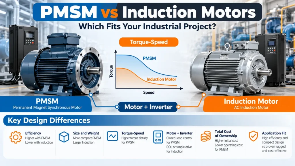
A permanent magnet synchronous motor (PMSM) may be the better choice when documented efficiency, compact packaging, or variable-speed performance justifies its installed cost. An AC induction motor may be preferable when direct-on-line (DOL) operation, an established replacement design, service familiarity, or a limited capital budget matters more. Neither technology is automatically superior. The choice depends on the actual torque-speed duty, operating hours, electrical and mechanical interfaces, and total cost of ownership (TCO).
For industrial engineers, OEM equipment designers, and procurement teams, the most useful comparison is not motor type versus motor type in isolation. It is one technically feasible motor-and-drive system versus another, evaluated at equivalent shaft output and realistic operating conditions. This guide explains the engineering differences, identifies situations that favor each option, and shows how to calculate an illustrative energy-cost payback before requesting quotations.
PMSM vs Induction Motors: Key Differences at a Glance
A PMSM uses permanent magnets to establish its rotor magnetic field. A conventional squirrel-cage induction motor develops rotor current through electromagnetic induction. That distinction changes the motor’s loss mechanisms and its typical control arrangements, but does not establish the winner for a particular project.
| Selection factor | PMSM | Squirrel-cage induction motor |
|---|---|---|
| Rotor field | Established by permanent magnets | Created through currents induced in the rotor |
| Running speed | Synchronous with the rotating stator field in normal synchronized operation | Operates with slip in normal motoring operation |
| Rotor losses | Avoids induction-type rotor copper losses; other losses remain | Rotor conductor losses contribute heat |
| Efficiency | Can be especially attractive where actual duty-point data supports an advantage | Modern efficient models can also deliver strong rated and part-load performance |
| Starting arrangement | Most inverter-driven industrial models need a compatible drive; special line-start designs exist | Suitable designs can start DOL or operate with a VFD |
| Speed control | Requires a supported control strategy; an encoder is not always necessary | VFD control is common for variable speed; DOL is an option for suitable fixed-speed service |
| Torque density / size | Certain models offer more compact packaging | Size depends on rating, frame design, cooling, and speed |
| Thermal considerations | Check magnet temperature margins, winding insulation, and cooling | Check rotor heating, insulation, bearings, and cooling |
| Initial installed cost | May be higher after drive and integration are included | Standard DOL replacements may offer a lower initial installed cost |
| Best-fit conditions | Verified efficiency benefits, long-duty operation, compact OEM designs | Standard replacements, suitable DOL installations, familiar service infrastructure |
How to use the table: First eliminate any option that cannot meet startup torque, load inertia, speed range, mechanical fit, or thermal requirements. Then compare the remaining options on measured or manufacturer-documented efficiency, installed cost, and service risk. Do not award a motor the project solely because its published peak efficiency is higher.
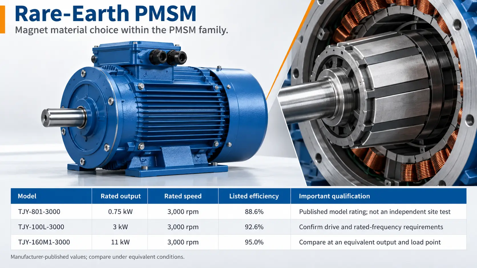
Core Technical Differences: Rotor Physics, Slip, and Losses
The differences between these motor types begin with how their rotors generate magnetic flux and torque. Understanding induced rotor current and slip helps explain the different loss patterns, but those mechanisms only support selection when considered alongside the required operating speed, load profile, and control system.
Permanent Magnet Excitation vs Induced Rotor Current
The PMSM rotor carries permanent magnets that provide magnetic excitation. Under normal synchronous operation, it does not need induction-type rotor current to establish that field. Avoiding that component of rotor copper loss can improve efficiency and reduce heat generated in the rotor. The motor still incurs stator winding losses, iron or core losses, mechanical losses, and potentially additional losses associated with harmonics and operating conditions.
In a squirrel-cage induction motor, the stator’s rotating magnetic field induces current in the rotor conductors. The interaction of this current with the magnetic field produces torque. Because the rotor conductors have resistance, part of the electrical energy becomes heat. Rotor-current losses vary with slip, load, and motor design; they are not a fixed percentage across all induction motors.
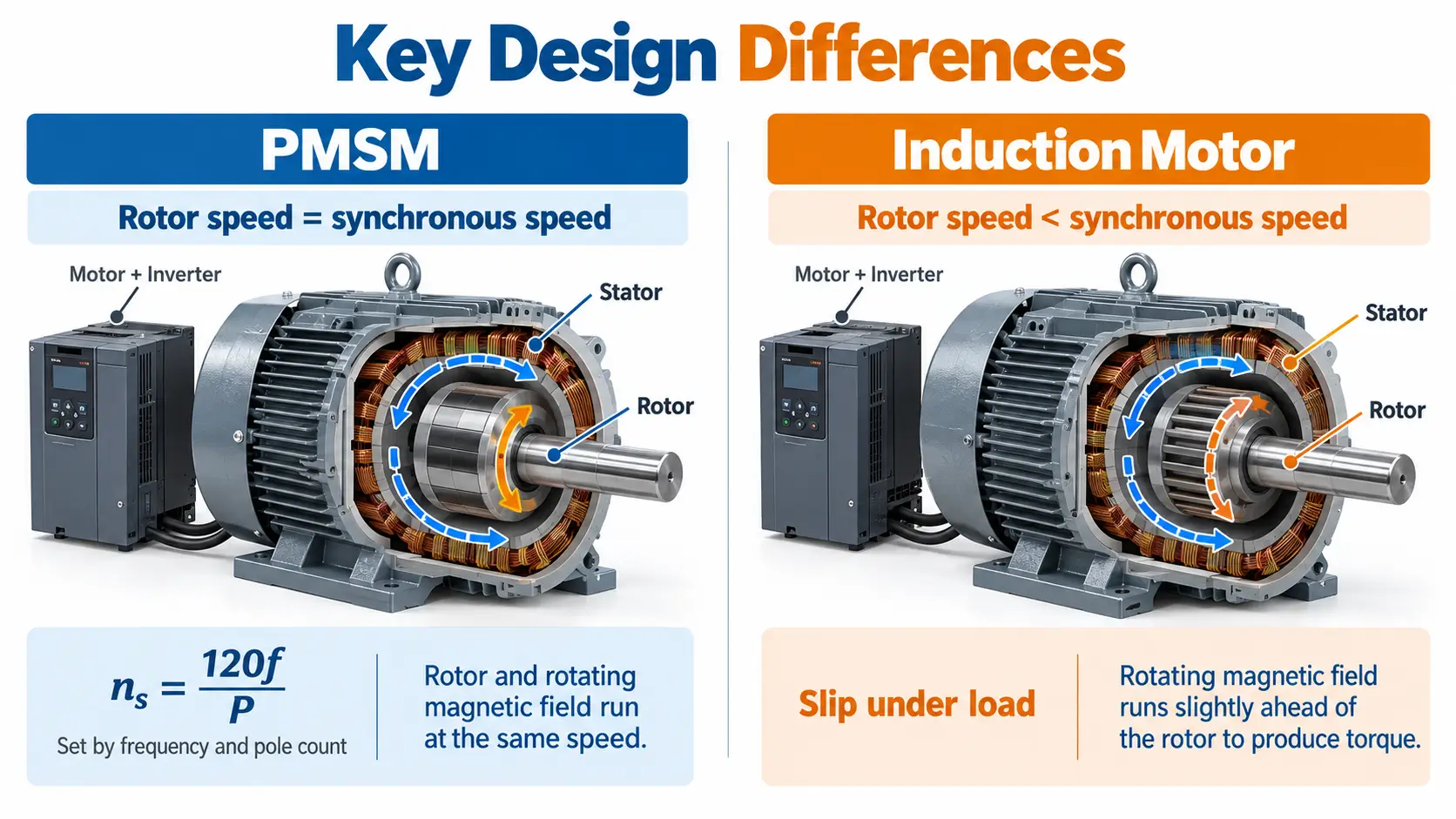
Synchronous Speed vs Induction Motor Slip
A PMSM rotates in synchronism with the stator’s rotating magnetic field when its operating conditions and control maintain synchronization. The synchronous speed is related to electrical frequency and pole count: nₛ = 120f / P, where nₛ is revolutions per minute, f is frequency in hertz, and P is the number of poles. A compatible inverter changes supply frequency to control speed.
An induction motor develops normal motoring torque with a difference between synchronous field speed and rotor speed, known as slip. Under load, the rotor typically turns slightly slower than the rotating field. A VFD can regulate induction-motor speed too. Therefore, synchronous operation alone is not proof that a PMSM will deliver better speed control or process performance in every application.
What the Physics Means for the Project
The design distinction matters because motor losses affect cooling, efficiency maps, and the continuous-duty operating envelope. But rotor copper loss is only one component of system loss. A reliable comparison needs both vendors’ performance data at the same shaft-power, speed, and duty points, not a general statement that one technology “has no losses.”
Efficiency and Energy Consumption: Compare Operating Points, Not Headlines
Motor efficiency is most useful when evaluated at operating conditions that reflect the actual machine duty. This section separates rated efficiency from performance across the load range and explains why drive losses must be included before judging whether either system will meaningfully reduce annual electricity costs.
Rated Efficiency Is Not a Universal Range
PMSMs can reach high efficiency in suitable designs because they avoid induction-type rotor copper loss. However, induction motors are available in high-efficiency configurations as well. Quoted ranges such as 93%–97% for PMSMs and 90%–95% for induction motors may describe selected products; they are not universal, cross-industry efficiency bands. Motor size, pole count, speed, winding design, cooling, test method, and rated output all affect the result.
Compare the exact manufacturer model, rated shaft power, speed, test conditions, and stated efficiency. The applicable standard also matters. IEC 60034-30-1:2025 covers efficiency classes of line-operated AC motors within its defined scope; IEC TS 60034-30-2:2016 addresses variable-speed AC motors within a different scope. An efficiency class should not be mistaken for a guaranteed efficiency percentage for every motor or application. [1][2]
Part-Load Efficiency and Duty Cycle
Many industrial systems do not run continuously at rated output. A ventilation fan may spend most of its day at reduced demand; a process pump may operate at several flow setpoints; a compressor’s load profile depends on its control scheme. A motor that performs well at its rating may have a different advantage—or none—across the actual duty profile.
Ask each vendor for efficiency or loss data at representative speed-and-torque points. Estimate the hours spent at each point from controls logs, process data, or a defensible design profile. For variable-flow machines, compare the complete pumping or ventilation arrangement: changing speed can alter the mechanical power required, which must be held consistent across the motor options.
Complete Motor-Drive System Efficiency
A VFD provides speed control but consumes power. Filters, transformers, cooling equipment, and other auxiliaries may add losses depending on the architecture. Comparing a PMSM motor-only efficiency figure to the wall-plug efficiency of an induction motor with a VFD would be misleading. IEC 61800-9-2:2023, including its 2025 amendment, addresses power-drive-system losses and efficiency classification, taking operating points into account. [3]
The practical comparison rule is simple: same mechanical duty, same system boundary, same annual load profile. Use matching electrical-input estimates for complete solutions, and do not credit one motor architecture for process savings caused primarily by adding speed control to a previously fixed-speed system.
Starting Performance, Motor Size, and Environmental Reliability
An efficient motor can still be unsuitable if it cannot accelerate the load, fit the available space, or withstand the installation environment. The following checks connect starting torque, physical dimensions, and thermal limits to the requirements that determine whether a proposed motor can work reliably in the project.
Starting Torque, Acceleration, and Load Inertia
Conventional induction motors can be designed for DOL operation where the supply and driven load permit it. DOL starting can impose substantial inrush current and offers limited control of acceleration; a VFD can provide controlled startup and adjustable speed. Many industrial PMSMs are designed for inverter operation. Line-start PMSMs exist but are a distinct product category whose starting torque and permissible load inertia still require verification.
For conveyors, mixers, and other demanding loads, request torque-speed curves, starting and pull-out or overload capability, acceleration limits, and duty ratings. A motor that meets steady-state power requirements may still be unsuitable for the required start or acceleration. Match the motor-plus-drive torque envelope to the machine’s load torque and inertia rather than assuming that high torque density guarantees startup capability.
Torque Density, Frame Size, and Mounting
Some PMSM designs achieve high torque or power density, allowing a smaller package for a defined output. That can be valuable in compact OEM equipment, tight machine rooms, and integrated skids. But claims such as a motor being “one-third smaller” apply only when supported by an actual like-for-like product comparison. A universal size or weight reduction should not be claimed.
Before approving a substitution, compare the complete assembly: flange and frame dimensions, shaft center height, couplings, bearings, cooling configuration, enclosure, and access for maintenance. A smaller motor is not automatically cheaper to install if the replacement requires a different drive, mounting plate, or cooling arrangement.
Thermal Limits, Maintenance, and Ruggedness
A PMSM’s magnetic material has temperature-dependent properties. Its allowable operating envelope depends on magnet grade, coercivity, design margin, overload history, and thermal management. Uncontrolled temperature or severe operating conditions may raise irreversible demagnetization risk; there is no single safe or unsafe temperature applicable to all PMSMs. Ask for the manufacturer’s continuous and peak thermal limits.
Induction motors do not have permanent-magnet demagnetization risk, but still face rotor heating, winding insulation limits, bearing wear, contamination, and cooling constraints. Either motor type may be built for demanding environments. The deciding evidence is the specific model’s environmental and thermal rating, plus repair options, spare parts lead time, and the site’s service capability—not an unsupported blanket claim that one technology is universally more rugged.
VFD Requirements and Retrofit Compatibility
Control hardware can change both the feasibility and the installed cost of a motor selection. Before considering a PMSM as a replacement for an induction motor, engineers should verify drive support, feedback needs, electrical protection, and the modifications required to integrate the complete system.
Does a PMSM Need a VFD or Encoder?
Many industrial PMSMs use an inverter designed to control permanent-magnet motors. Conventional induction motors may connect to a suitable grid supply without a VFD, although VFDs are common where adjustable speed or controlled starting is needed. Special line-start PMSMs are an exception to the usual inverter-driven PMSM arrangement and should be evaluated under their own product documentation.
An encoder is not universally required for a PMSM. Some industrial drives support sensorless operation, estimating rotor position and speed from electrical measurements. Whether sensorless control meets the required low-speed torque, positioning, functional safety, or dynamic response depends on the actual application. For example, ABB’s ACS180 family supports both induction and permanent-magnet motors and offers sensorless vector control; Danfoss describes both sensorless and encoder-based strategies in its iC7 range. [4][5]
Retrofitting an Existing Induction-Motor Installation
Do not assume an existing induction-motor VFD can operate a PMSM. Verify supported motor technology, supply voltage, rated current, overload capacity, control mode, feedback, motor parameters, and commissioning functions. Some drives support both architectures; others do not, and capability can differ by model or firmware.
Mechanical checks are equally important: mounting patterns, shaft dimensions, alignment, cooling, cable length, electrical protection, and integration with the machine’s PLC or control system. Price every required change—including new drive hardware, wiring, filters, mounting components, labor, and commissioning—before comparing installed cost.
Electrical Protection and Commissioning
VFD installations may require evaluation of electromagnetic interference, motor terminal voltage stress, grounding, bearing currents, cable length, and harmonic mitigation. These issues depend on the converter and installation, not on the PMSM label alone. Review the applicable drive instructions and system requirements instead of assuming every retrofit needs the same external filter or encoder.
Ask suppliers to document motor identification or tuning steps, protection settings, acceptable cable arrangements, startup testing, and acceptance criteria. A technically attractive motor is not an operational improvement if the machine cannot be commissioned and supported reliably.
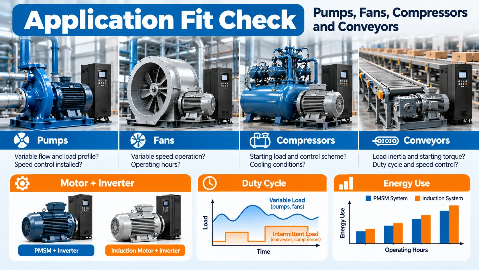
Application Fit: Pumps, Fans, Compressors, and Conveyors
Application names are useful starting points, but load torque, speed range, and operating hours—not the equipment label alone—determine the best motor architecture.
| Industrial application | Critical project questions | Practical selection direction |
|---|---|---|
| Pumps and fans | Is flow variable? What is the speed/load-hour profile? Is speed control already installed? | Compare full motor-drive energy use across the duty profile; do not assume PMSM savings without data. |
| Compressors | What starting load, control scheme, operating hours, and cooling conditions apply? | Verify starting/overload capability, drive integration, and performance at actual operating points. |
| Conveyors | What are the load inertia, starting torque, duty cycle, and speed-control requirements? | Prioritize starting torque, controlled acceleration, and serviceability; compare efficiency after feasibility. |
| Mixers and process machinery | Does the application demand continuous low-speed torque or frequent load changes? | Compare motor-drive torque curves, thermal limits, and control accuracy. |
| Compact OEM and HVAC skids | Are installation space, acoustic performance, and electrical controls constrained? | Evaluate model-specific motor dimensions, motor-drive efficiency, and integration costs. |
| Standard industrial replacements | Are DOL supply, existing VFD, mounting, and maintenance arrangements fixed? | Verify like-for-like induction replacement first, then test whether conversion offers meaningful TCO benefits. |
For a variable-flow pump, the main energy opportunity may result from changing operating speed rather than exchanging rotor technologies. If both candidates use properly matched VFDs, compare their electrical input at each operating point. For a constant-speed conveyor, starting torque, duty cycle, and maintainability may be decisive even if an alternative motor has a higher rated efficiency. These distinctions prevent a general motor comparison from becoming an inappropriate product recommendation.
When Should You Choose Each Motor Type?
Motor selection is a conditional decision rather than a ranking of technologies. The following guidance translates efficiency, installation, service, and budget considerations into practical screening rules, while keeping mandatory torque, thermal, and control requirements ahead of projected operating savings.
When a PMSM May Be the Better Choice
Evaluate a PMSM first when the machine runs many hours, energy costs are material, documented efficiency maps show a real advantage, or high torque density offers important packaging benefits. It is especially worth investigating for a new OEM design where the correct inverter, controls, and mounting arrangement can be selected together rather than retrofitted later.
However, the PMSM must still pass startup, overload, thermal, and serviceability checks. Short annual run time, insufficient energy savings, expensive drive replacement, magnet temperature concerns, or limited repair infrastructure can eliminate an apparent benefit. A technical advantage becomes a project advantage only when it survives complete system costing and reliability review.
When an Induction Motor May Be the Better Choice
An induction motor may be the practical option for a compatible replacement, a suitable DOL installation, or a project where standard parts, familiar maintenance, and lower upfront system cost are priorities. A high-efficiency induction motor can also be a strong choice in variable-speed service when supported by an appropriate VFD and documented load-point efficiency.
Do not replace a reliable induction motor solely because another motor type has a higher published peak efficiency. Compare the anticipated annual savings with all conversion costs and operating risks. Conversely, do not reject PMSM solely because its motor price is higher if the process operates continuously and a documented energy advantage makes the system economics favorable.
Quick Selection Rules
- High operating hours + measured system-efficiency advantage: evaluate PMSM payback.
- Existing DOL infrastructure + compatible duty: induction motor is a sensible baseline; examine line-start alternatives if justified.
- Demanding startup or wide speed range: compare complete motor-drive torque and control capability first.
- Tight equipment envelope: compare actual dimensions and cooling, not generic technology claims.
- Harsh environment or critical uptime: prioritize verified ratings, maintenance support, and spare parts for either option.
- Small or uncertain energy savings: favor the technically compliant solution with the better total installed and lifecycle cost.
Total Cost of Ownership: CAPEX, OPEX, and Energy Payback
Once both motor options satisfy the technical requirements, the decision also depends on lifecycle economics. Motor price alone does not capture drive integration, electricity consumption, maintenance, or downtime, so this section defines consistent cost boundaries and demonstrates how to calculate savings and payback from explicit assumptions.
Define Comparable System Boundaries
CAPEX includes the motor, VFD when needed, controls, cables and protection, mechanical changes, installation, commissioning, and any additional auxiliary equipment. OPEX includes electricity, scheduled maintenance, expected repairs, spare parts, and economically material downtime. A comparison is not fair if one quote includes new drive hardware and commissioning while the other excludes them.
When the machine must deliver the same constant mechanical output at a fixed operating point, a simple annual electricity-cost estimate is:
Annual electricity cost = [shaft output power (kW) ÷ (motor efficiency × drive efficiency)] × annual operating hours × electricity price ($/kWh)
Use efficiencies expressed as decimal fractions. For a genuinely DOL system without a VFD, the drive-efficiency factor is 1.0; include any other material electrical or auxiliary losses consistently. For variable loads, calculate each operating point separately:
Annual energy (kWh) = Σ [shaft output power at point i ÷ (motor efficiency at i × drive efficiency at i)] × hours at point i
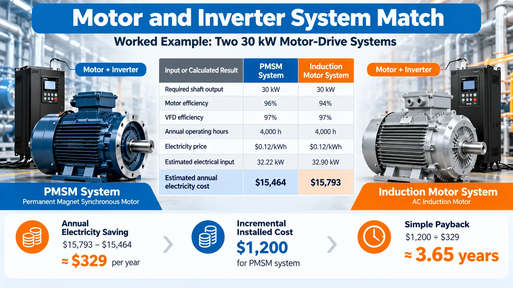
Worked Example: Two 30 kW Motor-Drive Systems
Consider two hypothetical systems delivering 30 kW of mechanical shaft output continuously at the specified operating point for 4,000 hours per year. Both alternatives use a VFD with assumed 97% efficiency. For illustration only, the PMSM motor efficiency is 96%, the induction motor efficiency is 94%, electricity costs $0.12/kWh, and the fully installed PMSM solution costs $1,200 more. These are assumptions, not verified quotations or universal efficiency claims.
| Input or calculated result | PMSM system | Induction motor system |
|---|---|---|
| Required shaft output | 30 kW | 30 kW |
| Assumed motor efficiency | 96% | 94% |
| Assumed VFD efficiency | 97% | 97% |
| Annual operating hours | 4,000 h | 4,000 h |
| Electricity price | $0.12/kWh | $0.12/kWh |
| Estimated electrical input | 32.22 kW | 32.90 kW |
| Estimated annual electricity cost | $15,464 | $15,793 |
The estimated annual electricity saving is about $329. With an incremental installed cost of $1,200, the illustrative simple payback is $1,200 ÷ $329 ≈ 3.65 years. The calculation is reproducible from the stated assumptions; it does not establish that a real PMSM and induction motor pair will achieve those efficiencies under the same load profile.
What Changes the Financial Decision?
Real projects need a multi-point duty profile, not only one rated-power calculation. Results may change with energy tariffs, annual operating hours, drive losses, maintenance costs, downtime probability, service life, and replacement costs. If the two motors operate with different control strategies, also evaluate whether they meet the same process duty rather than attributing a change in process energy entirely to motor efficiency.
Simple payback = incremental installed cost ÷ annual net operating savings. If annual net savings are zero or negative, there is no positive simple payback. A fuller TCO or net-present-value analysis should account for future costs and the time value of money where material. The U.S. Department of Energy’s motor-system resources similarly encourage assessing entire systems and provide tools for comparing annual motor-drive energy costs. [6]
Decision rule: Choose the lower-lifecycle-cost system only after confirming that it meets the project’s mandatory engineering requirements, and only if its assumed savings, service requirements, and capital commitment fit the owner’s financial criteria.
Final Motor Selection Matrix and RFQ Checklist
The final step is to translate the technical and financial comparison into a repeatable selection process. Use the matrix to screen motor options against mandatory operating conditions, then prepare a consistent set of project information so suppliers can quote comparable motor and drive solutions.
Use a Two-Stage Selection Decision
First, check technical feasibility: shaft output, operating speed, starting torque, inertia, mechanical fit, thermal rating, electrical supply, drive compatibility, and acceptable environmental protection. Any motor-drive combination that fails a mandatory requirement should be removed from the shortlist regardless of claimed efficiency.
Then compare only the feasible options on actual operating-point energy consumption, installed cost, maintenance support, downtime risk, and expected lifetime. The following matrix is a screening guide—not a substitute for manufacturer approval.
| Project condition | What to evaluate | Direction |
|---|---|---|
| Long operating hours, high electricity tariff | Measured or published complete-system efficiency across actual loads | PMSM may offer better economics if savings exceed its cost premium |
| Existing DOL installation | Supply capacity, starting requirements, replacement compatibility | Induction motor often provides the simplest baseline |
| Restricted machine footprint | Actual motor dimensions, cooling, drive hardware, mechanical interfaces | Compare compact PMSM models against the full installation envelope |
| Existing VFD or control architecture | Supported motor types, drive sizing, feedback, firmware, commissioning | Do not assume PMSM interchangeability |
| High-inertia startup or frequent acceleration | Torque-speed and overload curves, thermal duty | Select on demonstrated motor-drive capability |
| High-temperature, dusty, or wet site | Temperature limits, IP rating, insulation, cooling, service conditions | Select model-specific ruggedness, not technology stereotypes |
| Limited budget and low operating hours | Full installed cost and realistic payback | A suitable induction system may be economically preferable |
What to Include in a Motor RFQ
Provide the same requirement package to each potential supplier so their proposed systems are comparable:
- Required shaft power (kW), torque-speed curve, rated and maximum speed.
- Starting torque, acceleration time, load inertia, and overload duty.
- Operating hours, speed/load profile, starts per hour, and duty cycle.
- Electrical supply, permitted starting method, existing VFD model, and control interface.
- Ambient temperature, altitude, contamination, cooling, protection rating, and installation location.
- Frame and mounting drawing, shaft dimensions, coupling, and space limits.
- Required efficiency data and stated test method at relevant operating points.
- Drive compatibility confirmation, electrical protection, and commissioning scope.
- Spare parts, service capability, warranty, delivery terms, and full installed-price inclusions.
Ask for motor data sheets, torque-speed curves, efficiency/loss maps, dimensional drawings, drive compatibility statements, thermal limitations, and a clearly scoped quotation. These are more useful for a project decision than a brochure claim that one technology is simply “more efficient.”
Conclusion: Which Motor Fits Your Industrial Project?
Choose a PMSM when its verified motor-and-drive performance, packaging, and lifecycle savings justify the system investment. Choose an induction motor when it better satisfies the project’s installation, startup, service, and budget constraints. The correct decision is conditional, and both technologies can be effective industrial solutions.
The next step is to document your actual machine duty, screen each motor-drive configuration against mandatory technical requirements, and request comparable supplier data. Once the motor options are technically feasible, use operating-point energy calculations and total installed cost to make the final procurement decision.
Technical References
- IEC, IEC 60034-30-1:2025 — Efficiency classes of line operated AC motors: https://webstore.iec.ch/en/publication/91195
- IEC, IEC TS 60034-30-2:2016 — Efficiency classes of variable speed AC motors: https://webstore.iec.ch/en/publication/30830
- IEC, IEC 61800-9-2:2023 + AMD1:2025 — Power drive system efficiency: https://webstore.iec.ch/en/publication/111276
- ABB, ACS180 drives — support for induction and permanent-magnet motors and sensorless control: https://www.abb.com/global/en/areas/motion/drives/low-voltage-ac-drives/machinery-drives/acs180
- Danfoss, Motor control in the iC7 series: https://www.danfoss.com/en-in/about-danfoss/our-businesses/drives/about-ic7-series/motor-control/
- U.S. Department of Energy, Motor Systems: https://betterbuildingssolutioncenter.energy.gov/better-plants/motors
- U.S. Department of Energy, MEASUR motor drive and replacement calculators: https://www.energy.gov/cmei/amo/measur-calculator-list-and-descriptions